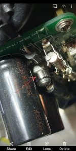
Yep, 1.78 on TP-105 to positive and 1.83 on TP-106 to negative. I'll move on to populating the outputs.

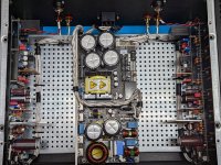
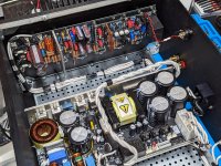
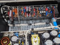
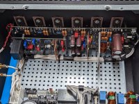
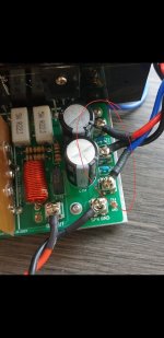
Chassis 3 finally complete, and I think the layout and wiring turned out the best on this one. Which means I will be redoing the first two! 🤣 . All 3 ended up being carbon copies of each other in respect to noise floor, distortion, response and gain. So that's 6 boards in total completed with no measurable variations between them.
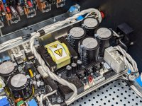
One thing I haven't talked about is the PFC frontend on the Microaudio SMPS I am using. I can lower my AC input voltage to less then 100 volts and still get the same output power as 120 volts. So if you live somewhere with bad AC or brownouts, it is something that should be considered. Very impressed with those supplies, and honestly this was my first Class AB build using a SMPS, and I don't see any negatives to the linear supplies and massive transformers I have used in the past.
One thing I haven't talked about is the PFC frontend on the Microaudio SMPS I am using. I can lower my AC input voltage to less then 100 volts and still get the same output power as 120 volts. So if you live somewhere with bad AC or brownouts, it is something that should be considered. Very impressed with those supplies, and honestly this was my first Class AB build using a SMPS, and I don't see any negatives to the linear supplies and massive transformers I have used in the past.
Attachments
-
 PXL_20220717_151808063.jpg615.9 KB · Views: 395
 -
 PXL_20220718_204941925.jpg745.7 KB · Views: 383
 -
 PXL_20220718_204948885.jpg634.3 KB · Views: 426
 -
 PXL_20220718_205001434.jpg680.3 KB · Views: 396
 -
 PXL_20220718_205009589.jpg625.7 KB · Views: 394
 -
 PXL_20220718_205017745.jpg653.4 KB · Views: 380
 -
 PXL_20220718_205025869.jpg663.1 KB · Views: 386
 -
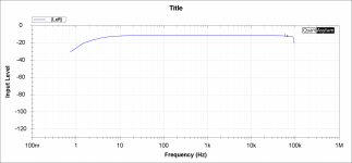 freq response.png237.6 KB · Views: 371
 -
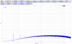 Noise A-Weighted.png334.1 KB · Views: 303
 -
 THD vs POWER.png18.7 KB · Views: 368
Beautiful!!
I recall one of the wiring guides in the amp documentation saying to keep the RCA inputs close together and tie the shields together to reduce mains noise - is this something that would be applicable to your amplifier or does the SMPS make that moot?
Now to really get this amp to get exposure - ship one over to ASR lol
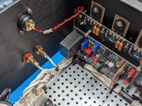
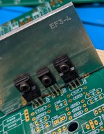
I felt one of the biggest time consuming parts on my build(s) were the heatsinks, so I found a local metalworker to lasercut them. I can ship worldwide from Canada. I have lots here and ready to go. I am only waiting on the extended length EF3-4 Driver heatsink.
Attachments
I would have kept them closer but the backpanel comes precut so that wasn't an option for me. Shipping there and back would be well over $200 plus packing it up. I trust the teams measurements and the ones I took, I don't see the need to send over there just to get on a SINAD ratings chart, which I do think this amp would rank in the top 2 or 3 anyhow. Actually considering the output power and gain of the amp, it beats them all in my opinion.Beautiful!!
I recall one of the wiring guides in the amp documentation saying to keep the RCA inputs close together and tie the shields together to reduce mains noise - is this something that would be applicable to your amplifier or does the SMPS make that moot?
Now to really get this amp to get exposure - ship one over to ASR lol
Attachments

Hi Guy's, just letting you all know that I added the heatsink pdf that @fireanimal created to the first post of the 2nd group buy thread.
Legend.I felt one of the biggest time consuming parts on my build(s) were the heatsinks, so I found a local metalworker to lasercut them. I can ship worldwide from Canada. I have lots here and ready to go. I am only waiting on the extended length EF3-4 Driver heatsink.
Agree re the 'SINAD' chart - it was more if anyone wanted to ignite interest in DIY amps, although not including the same protection features most commercial offerings do I suppose. ASR has certainly sold a boat load of hypex and purifi modules.
I felt one of the biggest time consuming parts on my build(s) were the heatsinks, so I found a local metalworker to lasercut them. I can ship worldwide from Canada. I have lots here and ready to go.
I sent you a PM regarding these.
Thanks,
Alan
And we have ignition!


Drilling the hole for the power switch scuffed up the anodizing on the right bottom corner. Any ideas how to fix that? I thought about a light black spray paint, but may make more sense to just have it re-anodized, if I can find a place to do it.
Drilling the hole for the power switch scuffed up the anodizing on the right bottom corner. Any ideas how to fix that? I thought about a light black spray paint, but may make more sense to just have it re-anodized, if I can find a place to do it.
Now time to assemble the second one and figure out the current overload function on the protection board I used.
Try black permanent marker and then wipe the excess offAnd we have ignition!
View attachment 1073851View attachment 1073852
Drilling the hole for the power switch scuffed up the anodizing on the right bottom corner. Any ideas how to fix that? I thought about a light black spray paint, but may make more sense to just have it re-anodized, if I can find a place to do it.
- Dan
I have lots here and ready to go.
I would be interested if you have any EF3-3.
Edit - never mind I see the PDF.
Nice looking build Richard.And we have ignition!
View attachment 1073851View attachment 1073852
Drilling the hole for the power switch scuffed up the anodizing on the right bottom corner. Any ideas how to fix that? I thought about a light black spray paint, but may make more sense to just have it re-anodized, if I can find a place to do it.
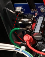
One suggestion.
Bring your power supply wires together as soon as possible to reduce the loop area. You may need a small stand-off like I used on my honey badger to get over the fuse.
Attachments
Agreed, I have used a larger permanent marker before but it depends on the severity of the scuff marks.I've tried sharpie but it didn't work great
Might be worth ordering a replacement panel or re-anodising
- Dan
- Home
- Amplifiers
- Solid State
- DIY Class A/B Amp The "Wolverine" build thread