Good questions and I probably should give more info.
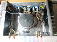
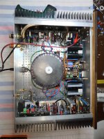
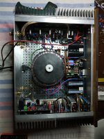
Heatsinks are in the chassis, upright and screwed to the chassis on the bottom, with about 1/2-3/4” of clearance.
My mains is a little high at 123-125VAC, but three other Antek transformers were all within 1-2 Vac on the secondaries, so 6V seemed excessive to me.
I also run 4 large 80V (100V peak) 33,000uF caps, no L or R or bleeders in the path, with a CL-60 from PSU 0 to chassis.
A tiny hiss from my tweeter with ear on top of tweeter, my DMM measures 0 AC, below it’s capabilities - so it’s silent.
My speakers are DIY 5-1/2” two-way with nominal impedance of 6.8r, so a very easy load for any amp.
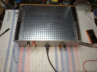
Really enjoying the amp, worth all the time, troubleshooting my oversights and mistakes to finally have it playing some music.
I will play it for a few weeks before I change the bias. My heatsinks are inside the case, so not ideal but does allow for more heat without risk of burns.
Thanks for the detail response.
Heatsinks are in the chassis, upright and screwed to the chassis on the bottom, with about 1/2-3/4” of clearance.
My mains is a little high at 123-125VAC, but three other Antek transformers were all within 1-2 Vac on the secondaries, so 6V seemed excessive to me.
I also run 4 large 80V (100V peak) 33,000uF caps, no L or R or bleeders in the path, with a CL-60 from PSU 0 to chassis.
A tiny hiss from my tweeter with ear on top of tweeter, my DMM measures 0 AC, below it’s capabilities - so it’s silent.
My speakers are DIY 5-1/2” two-way with nominal impedance of 6.8r, so a very easy load for any amp.
Really enjoying the amp, worth all the time, troubleshooting my oversights and mistakes to finally have it playing some music.
I will play it for a few weeks before I change the bias. My heatsinks are inside the case, so not ideal but does allow for more heat without risk of burns.
Thanks for the detail response.

Congratulations on getting your wolverine playing music Bullittstang!
People often get a bit concerned with heat when an amplifier is optimally biased since comparatively, commercial
amplifiers tend to be underbiased to save money on heatsinking.
If you are concerned you could change the resistor values per the build guide to suit the higher rail voltages
but you are still going to have the same sort of heat generated in the output stage unless you reduce rail voltage with a lower secondary voltage transformer
or reduce the bias.
I would resist the urge to reduce the bias too much.
Only issue is transformers are always going to be costly......
Maybe your wolverine is destined to be a bit of a hot-rod ?
- Dan
Alright I'm making waves on this amplifier project now, let the Frankenstein build begin. Just dummying up how everything is going to fit in the parasound chassis and there's a solid intermediate bar the existing output channels were "hanging" off, any objections to me mounting in a similar manner like pictured but I will add my own standoffs for the lower part of the PCBs to the heatsink? The PCB will not be contacting the intermediate there would be 4mm gap. The EF3-3 length works out real nice too. Apologies for the novice questions this is my first DIY amp (I have repaired many, don't worry I won't be asking how to solder)

I also noticed this, but it went unanswered - are the (much) cheaper 279-RR03JR43TB okay to use, as the BOM states these should be 470mOhm?Going through parts lists, resistors R120AB to R125AB the part numbers listed, any performance difference with the amplifier between these, 279-RR03JR43TB ( which are 430mOhms) and 71-CPF3.475%T00?
Mouser also listing the 603-FMP200JTF52-0R47 x5000 avail in October which could be a suitable alternative?
Last edited:

These aren't super important, as long as you stay away from wire-wound resistors and the size fits. 2-3W will be plenty of power handling. I use Metal Oxide Koa Speer from Mouser and have used them on 4 DIY amplifiers without issue.I also noticed this, but it went unanswered - are the (much) cheaper 279-RR03JR43TB okay to use, as the BOM states these should be 470mOhm?
Mouser also listing the 603-FMP200JTF52-0R47 x5000 avail in October which could be a suitable alternative?
660-MOSX3CT631RR47J - KOA Speer 0.47r 3W MOX, they are $0.46 --- these are a close fit with the big driver heatsink, but no real problem and didn't notch the heatsink, I just wrapped the bottom 1/4" with Kapton tape to be safe.
303-MOR02SJ047KB00 - Don't know anything about RoyalOhm company, but they have 2W MOX for $0.10, so might be worth getting some to see.
279-RR03JR47TB are the ones I am using for most emitter resistors. I bought 1000, as that was the minimum quantity. These are metal film in a 5% tolerance with a 300 ppm/C temperature coefficient. The CPF3 are 1% 200 ppm/C. Both are non-flammable and fusible. I used my 4-wire ohm meter to measure a bunch of these resistors and selected a group that was +/- 500 uohms. I then ordered the resulting group low to high, and took pairs from the outside (one from each extreme). This resulted in all of the emitter resistances +/- 50 uohms. Thus I have a very tight match on the 8 pairs for about half the cost of a single CPF3 resistor. I did spend 30 minutes matching resistors, though. The KOA/Speer MOX resistors also will work, and I have used those in the past. The only time I can see there being an advantage to the CPF3 is when driving low-impedance, low-efficiency loads where you might avoid a bit of thermal distortion at low frequencies. Or, of course, you just want to know you've got the very best possible. That's psychological and not performance based.🙂 PM me if you are interested in some of the above RR03 resistors. |
Thanks guys much appreciated, I’ll stick with the BOM 430mOhm resistors as I can get them now in my mouser order and not pay extra shipping, and I know the guys who put the BOM together know what they’re doing.
The TE and CPF3 are both fine the CPF3 is a premium option in that both temperature coefficient and precision are better as per post above
I would recommend the CPF3 if it suits your budget.
- Dan
I would recommend the CPF3 if it suits your budget.
- Dan
Heh, they are not in my budget, I'm recycling a chassis and hopefully output drivers - I'll stick with the 430mOhm 279-RR03JR43TB for now at around 7% the price. While I'm at it, I'm going full poverty spec build here with the cheapest alternatives for C4, C5 as the 5% micas, ceramic C0G for C-help, C118 and 119. I'm aware this may degrade performance, but I can always upgrade later when funds become available. Just hope the thing doesn't get unstable.
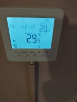
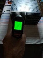
About temp......110-120 F. Ambient temp 29.5 C .The bias rich cold about 47-48 mv and settle down to 38-40mv at this moment the temp of the heatsinks are going down to 103 F.
Attachments

Wolverine stats.
Are there any stats being kept or being aquired such as:
Finished (effectively) builts per region: NA, SA, EU, ASIA or AU, NZ etc....Maybe some high level specs added such as drivers, outputs, power-supplies choices etc...
Note: Dont want to put up somebody in getting all the data but it would be nice to know what the geographical range and density of the Wolverine is and might become🙂
w.
I thought I was the only one who retrofitted these DIY amps into old E-waste ? Cool , this is another design consideration for myAlright I'm making waves on this amplifier project now, let the Frankenstein build begin.
new "mini" OPS's. I do have a Wolverine EF3 board I will use as a sub amp , with my tiny IPS's I will have tremendous flexibility to make
custom adaptations.
I might even make use of my dual SIP 14X IPS connection scheme , a common PC female ribbon cable can connect IPS/OPS.
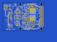
Very small (2/3rd's of a credit card - below) IPS's allow tight packing of many amps in the same box.
PS - "Infidel" = simpler wolverine IPS....
Attachments
First listening.... mobile phone record.
Guys-
IPS boards are assembled and ready to test! (Woot!)
In Dan's excellent video, it appears that he is test feeding the IPS board with about 30V (as judged from the display on the power supply). Once the amp is assembled, the V+ will be closer to 60V. Is 30V sufficient for testing?
The build guide mentions that the testing voltage measurements should be made with floating ground. My bench power supply has a ground lug in addition to the + and - terminals. Does this mean that I should not connect the ground terminal on the IPS board to the ground terminal on the power supply?
Appreciate the guidance!!
Jon
Well done Nikos, and nice choice of music too.First listening.... mobile phone record.
Hi Jon,Guys-
IPS boards are assembled and ready to test! (Woot!)
In Dan's excellent video, it appears that he is test feeding the IPS board with about 30V (as judged from the display on the power supply). Once the amp is assembled, the V+ will be closer to 60V. Is 30V sufficient for testing?
The build guide mentions that the testing voltage measurements should be made with floating ground. My bench power supply has a ground lug in addition to the + and - terminals. Does this mean that I should not connect the ground terminal on the IPS board to the ground terminal on the power supply?
Appreciate the guidance!!
Jon
I used 2 supplies to achieve +/- 60Vdc rails.
You leave the ground lug on the psu out and use the 0V terminal in between the "rails"
Hope this helps
- Daniel
- Home
- Amplifiers
- Solid State
- DIY Class A/B Amp The "Wolverine" build thread