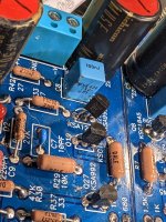
alright alright my boards were dirty i know i know. I marked one board blue(working) and the other red(not working) the led was installed reversed polarity (not the power). picture of q23(not melted) q25(not shorting) and the bottom of q19 but i did touch up the joint on top
Attachments


Another check would be to measure the voltage across the resistors that are in the path of current flow to see which transistors are working or not working: R11, R12, R7, R13, R15, R5, R2, R6, R14, R1, R4.
non of my transistors appear to be shorting out(sorry if that incorrect terminology, all the 3 legged guys, both through hole and smd) all in in the correct spots facing the right way, traces all connect where they are supposed too, seems everything is identical to the other working half, ill reconnect it to the power supply later and take some measurements. I have all the parts for the bigger outputs maybe ill swap those all in and see if that makes a difference too.
i was able to. im about to hook it back up for testing,Can you adjust the DC offset in both the positive and the negative direction?
when measuring "the voltage across" something thats with ground lead of mutimeter on the ground terminal and measuring the voltage on the leg of that component? or something else?
Voltage across a resistor is measured with a multimeter probe at each leg of the resistor.

r11 .32Another check would be to measure the voltage across the resistors that are in the path of current flow to see which transistors are working or not working: R11, R12, R7, R13, R15, R5, R2, R6, R14, R1, R4.
r32 .217
r12 .32
r33 .217
r7 2.283
r38 .037
r13 1.936
r31 .130
r15 25.22
r30 28.71
r5 .085
r37. 085
r2 0
r28 .05
r6 5.9
r36 .001
r14 1.752
r261.73
r1 .05
r27 0
r4 .085
.085
soo jfets q2 and q22 are suspect? also p1 and p1 have no effect on anything.
Does one channel work or are both channels not working?
Looking at your measurements I assume the unit of measure is Volt. Always include the unit of measure. Are the second measurement at each location from the "red" channel?
Starting from the signal input side, R1= 0.05V indicates Q5 and Q1 are functioning, although the current through them are approximately double the design value. On the other channel R27=0 indicates either Q23 or Q22, or both, are not working (Q5 and Q1 as shown on schematic).
R2=0V and R28=0.05V seem to indicate the other channel not working, that is, either Q2 or Q6 or both are not working. Is this the case - both channels are not working?
These circuits affect the function of the later circuits so they need to be fixed before assessing the rest of the board.
Suspect 1: Q1, suspect 2: Q2, suspect 3: Q3, suspect 4: Q4, suspect 5: bipolar orientation. Suspect 6: LED. Always. Perhaps not, but almost 
so removed and cleaned q1 q4 q22 and Q23Does one channel work or are both channels not working?
Looking at your measurements I assume the unit of measure is Volt. Always include the unit of measure. Are the second measurement at each location from the "red" channel?
Starting from the signal input side, R1= 0.05V indicates Q5 and Q1 are functioning, although the current through them are approximately double the design value. On the other channel R27=0 indicates either Q23 or Q22, or both, are not working (Q5 and Q1 as shown on schematic).
R2=0V and R28=0.05V seem to indicate the other channel not working, that is, either Q2 or Q6 or both are not working. Is this the case - both channels are not working?
These circuits affect the function of the later circuits so they need to be fixed before assessing the rest of the board.
View attachment 1173867
r1 .025v
r27 .003v
r14 1.736v
r26 1.715v
was able to use p1 and p2 adjust r6 to 1.71v and r36 to 1.713v
What are the two unmarked plated through-holes near P1 on the circuit board for? After I stuffed the board, they stood out like wallflowers at a dance, but seemed to both be at ground potential. For that reason, I tied them together with a jumper, and used that as a ground return point for the negative lead that connects to my three input sources (the six negative terminals are tied together with a buss wire, and this lead connects to that buss). I tried to search this thread for an answer, but my success rate with searching on diyAudio is next to zero these days. It used to be much easier to search with the old software; what happened?
It's just a courtesy connection point to tie both grounds together or not. Some builders use a single supply for both channels, others go dual mono with a separate supply for each channel.
R27 at 0.003V is still not good.
You needed to do more than clean Q22 and Q23. Did you test them while they were out?
I am puzzled. R27 is not good but R26 and R36 are good. Perhaps Q22 is bad? Or perhaps 0.003V at R27 was a mistake? Confirm R27 is 10R.
I assume the channel is still not working?
Asking again, was it just one channel not working or were both channels not working? And now?
Not enough information provided.
the small channel with smaller numbers q1 q2 etc was working yes but for all i know it wasn't working well, i didnt listen to it for long. all these meusurments have been taken with r16/r43 removed. ill remove all the jfets and test them. diode funtion on the multimeter correct? i bought extra jfets i even checked my invoice but i dont know where they went. I ordered 10 more just in case.
Do not remove all of them. Only remove the one that is suspect and test and replace if necessary.
Then test and hopefully that part of the circuit works and then move on down the line with the measurements. You may damage good parts by de-soldering and re-soldering.
If the other channel is working, do not take it apart. You can check voltages to determine if it is working to specifications. Only remove a part if voltages show a part possibly not working properly.
Google "testing a jfet with a multimeter" and you will find a lot of information.
Thank you william2001 for your response. Now that I think about it, those holes did kind of remind me of the ones on the Universal Power Supply board for the F5, F6, and other FW amps--- the holes that need jumpers to connect the two sides of the board, if one is not going to split the board vertically.
- Home
- Amplifiers
- Pass Labs
- Wayne's BA 2018 linestage