
Following up on my post #3733 the other day, I'm still wondering if a simple SPST switch between the wipers of two single pots (left and right volume controls) will work for me on my Wayne's Line Stage as a stereo/mono switch .
The reason I want one: Other than, for example, the stellar recordings of Rudy Van Gelder (for Blue Note, and some other labels) a lot of early jazz recordings sound better on mono, even when they say "stereo" on the cover. On these recordings, there is no real stereo soundstage imaging, the bass player seems to reside in one speaker and the piano player in the other, etc. Or, on more modern music, for example on the Groove Salad streaming music from SomaFM out of San Fransisco, the "modulation" of instruments back and forth from one channel to the other is sometimes so overdone that it can make me dizzy. In these cases, mono is a better option for me.
The reason I want one: Other than, for example, the stellar recordings of Rudy Van Gelder (for Blue Note, and some other labels) a lot of early jazz recordings sound better on mono, even when they say "stereo" on the cover. On these recordings, there is no real stereo soundstage imaging, the bass player seems to reside in one speaker and the piano player in the other, etc. Or, on more modern music, for example on the Groove Salad streaming music from SomaFM out of San Fransisco, the "modulation" of instruments back and forth from one channel to the other is sometimes so overdone that it can make me dizzy. In these cases, mono is a better option for me.
Thank you, Zen Mod, for confirming this method of getting a switchable mono signal! When the source material warrants, it will make listening more enjoyable for me on my Line Stage.
Hello,
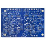
I have finished the line amplifier. The measurement results correspond to the publications very good, thanks to Wayne.
One question: Is the right value of R15 47k or 100k?
Thanks
Peter
I have finished the line amplifier. The measurement results correspond to the publications very good, thanks to Wayne.
One question: Is the right value of R15 47k or 100k?
Thanks
Peter
That emitter-follower stage there (Q7,Q11) is a nice touch (VAS beta enhancement), and the output stage also buffers the VAS collectors. Simple but very high performance belt and suspenders approach.... I like it.
Last edited:
Everyone's gotta start somewhere, this is my first "build". Everything went mostly smooth during assembly I thought, on initial turn on the " red board''s led did not fire up, I found I had installed it backwards, I flipped it and now it lights up but that board doesn't output any sound just some faint popping, the other board lights up and works great. I went through and reflowed the solder on all the joints and still have the same outcome. Gotta put in a order to digikey today so if I need some parts I can grab them. Any wanna walk me through trouble shooting?

Well, what's with the big electrolytic in lieu of the 0.1 that it replaced? I haven't looked at the board in ages but it looks like you replaced a NP with a polarized capacitor?
I think the input stage of this project tends to give people problems, particularly beginners. Q1-Q4 are tricky to install properly, and any trapped residue under them doesn't help either. My post at #1246 might be helpful. I didn't mention there how I also use compressed air as part of the cleaning process, to help move the contamination from underneath components. And I've been using a kids electric toothbrush (Paw Patrol 🐕🦺) as part of the cleaning process too, thanks Mark J. for the suggestion. Once I'm sure those SMD's are perfectly installed, I would want to know how much current is flowing through them. Check voltage across R4. Use ohm's law to calculate the current. Do the same for R5. (I'm talking about R4 and R5 in reference to post #1 of this thread) Should be a couple of milliamps? I can't remember exactly what Wayne chose there, maybe someone can help me. Beyond that, problems could be swapping an NPN for a PNP, wrong resistor placement / value, a solder short, etc. A very careful visual check and inspection is always the very first step in troubleshooting.
Last edited:
Naw they moved that cap there on the blue boards I think to make room for mounting hardware.Well, what's with the big electrolytic in lieu of the 0.1 that it replaced? I haven't looked at the board in ages but it looks like you replaced a NP with a polarized capacitor?
Attachments
re soldering...
With the exception of the surface-mounted transistors, I would have expected that all soldering occur on the reverse side of the board, no? Even re-flow work?
The heat damage to several of the caps and transistors might be a factor in the performance.
With the exception of the surface-mounted transistors, I would have expected that all soldering occur on the reverse side of the board, no? Even re-flow work?
The heat damage to several of the caps and transistors might be a factor in the performance.
I would start with Q23, it looks melted. Then twist Q25 to make sure the legs aren't shorted, finally, Q19 has one pad with no solder on it in your photo.Any wanna walk me through trouble shooting?
The big electrolytic caps have red on top.What do you mean by ‘red board’?
Everything went mostly smooth during assembly I thought, on initial turn on the " red board''s led did not fire up, I found I had installed it backwards, I flipped it and now it lights up but that board doesn't output any sound just some faint popping, the other board lights up and works great.
It seems that "installed it backwards" referred to reversed power supply polarity.
The electrolytics do not look damaged by the reversed polarity. But possible damage to some transistors?
I was under the impression that "installed backwards" was the LED itself (easy mistake to make). Speaking of, I verify those with the diode check feature of my DMM. It will light the LED when you get the polarity right...
- Home
- Amplifiers
- Pass Labs
- Wayne's BA 2018 linestage