That is perfectly true Pano, yes!Millions of people eat at McDonalds and don’t complain. It’s not wrong to want something better.
However, it does come down to each individual's desires and personal preferences, among other things.
And that of course is all over the universe in its depth.
Yes Nick, I remember building a 2 tube phono preamp with passive RIAA in between the gain stages about 40 years ago. It was one of the best I ever had. 🏁

Has some more noise but the benefit of crazy overload margin due to running on HV. It can also be triode when JFETS are like pentodes without heaters. Unless you got some exotic SIT stash.Yes Nick, I remember building a 2 tube phono preamp with passive RIAA in between the gain stages about 40 years ago. It was one of the best I ever had. 🏁
This circuit (from post #1) is a classic based on 1970's three transistors are enough type philosophy when they were quite expensive. But I took the challenge.
First, the OLG is likely to be low, so I calculated that. It came out at around 3300.
Then I considered that the output was effectively a high output impedance with a 12k load in parallel with the feedback network, so I changed the gain to a transconductance which worked out at about 0.332 A/V.
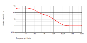
Then to establish a crude transfer function for the OLG I ran the frequency spectrum and that raised the first problem. The low frequency cut-off was too high to generate a respectable LF RIAA curve, so the gain needed to be increased. THe culprit was the 47 uF capacitor bypassing Tr2 emitter. That was a very common error for designers using the emitter resistor as the LF determining point rather than re, the small signal emitter impedance which at around 1mA is 25 ohms.
Thus, raise this to 220uF.
Next the HF point seemed very low, and the Miller capacitor high for such low current operation. Eliminated the 100pf and it seemed perfectly stable, but I haven't checked that.
The -3dB OLG points were then 24ms and 0.3us.
Then set the target gains at four frequencies and use Newton to home in on the values.
Result:
275k and 12.8nF; 20.3k and 3.73nF.
I hasten to add that just because this may be better (and I have not run the RIAA ideal against this to check yet) it could be that the rest of the circuit eliminated (for example) the peak in the original LF response.
Caveat: because the OLG is low the transistor gains will generate variations in the ideal components.
For stability if 10pF is needed for the Miller it makes little difference. 100pf shows a deviation and would need recalculating. I'd leave the 100pF out, or use as smaller cap as possible.
Centre gain measured 47.5 - that is 166mV for 3.5mV input at 1kHz.
Final edit: transistrs sim'd were grade B for gain.
First, the OLG is likely to be low, so I calculated that. It came out at around 3300.
Then I considered that the output was effectively a high output impedance with a 12k load in parallel with the feedback network, so I changed the gain to a transconductance which worked out at about 0.332 A/V.
Then to establish a crude transfer function for the OLG I ran the frequency spectrum and that raised the first problem. The low frequency cut-off was too high to generate a respectable LF RIAA curve, so the gain needed to be increased. THe culprit was the 47 uF capacitor bypassing Tr2 emitter. That was a very common error for designers using the emitter resistor as the LF determining point rather than re, the small signal emitter impedance which at around 1mA is 25 ohms.
Thus, raise this to 220uF.
Next the HF point seemed very low, and the Miller capacitor high for such low current operation. Eliminated the 100pf and it seemed perfectly stable, but I haven't checked that.
The -3dB OLG points were then 24ms and 0.3us.
Then set the target gains at four frequencies and use Newton to home in on the values.
Result:
275k and 12.8nF; 20.3k and 3.73nF.
I hasten to add that just because this may be better (and I have not run the RIAA ideal against this to check yet) it could be that the rest of the circuit eliminated (for example) the peak in the original LF response.
Caveat: because the OLG is low the transistor gains will generate variations in the ideal components.
For stability if 10pF is needed for the Miller it makes little difference. 100pf shows a deviation and would need recalculating. I'd leave the 100pF out, or use as smaller cap as possible.
Centre gain measured 47.5 - that is 166mV for 3.5mV input at 1kHz.
Final edit: transistrs sim'd were grade B for gain.
Attachments
Last edited:
Yes, no fear of clipping, to output could go very high because of the HV.crazy overload margin due to running on HV.
Also look at this thread,
https://www.diyaudio.com/community/threads/2n2222a-phono-preamp.158918/post-6392737
Many similarities
Hans
https://www.diyaudio.com/community/threads/2n2222a-phono-preamp.158918/post-6392737
Many similarities
Hans
Here's one I designed and built in 1979. I tweeked the EQ network a few yrs ago in LTspice, so its quite accurate now

Heres the conformance. Its about 0.5 dB 20 - 20kHz

Heres the square wave performance and loop gain - not as good as an opamp implementation, but this type of performance was pretty much standard back in the 1960's and 1970's. If you can reproduce a good square wave after passing the stimulus through and inverse RIAA, you can rest assured that the conformance of the equalizer if good.

Heres the conformance. Its about 0.5 dB 20 - 20kHz
Heres the square wave performance and loop gain - not as good as an opamp implementation, but this type of performance was pretty much standard back in the 1960's and 1970's. If you can reproduce a good square wave after passing the stimulus through and inverse RIAA, you can rest assured that the conformance of the equalizer if good.
Yes, they are.5532 op amps are as cheap as transistors now.
But that's got nothing to do with this bipolar design.
This article discusses Lipshitz's RIAA equations and findings https://hifisonix.com/wp-content/uploads/2015/01/RIAA-Equalization-Amplifiers-V2.0.pdf
Basically, what he found in 1979 was that most commercial all active RIAA EQ networks were up to 3-4 dB out, so he developed a set of equations to resolve the issues.
Basically, what he found in 1979 was that most commercial all active RIAA EQ networks were up to 3-4 dB out, so he developed a set of equations to resolve the issues.
Here's one I designed and built in 1979. I tweeked the EQ network a few yrs ago in LTspice, so its quite accurate now
View attachment 1165365
Is C9 supposed to be in parallel with R10 and if so, what's the idea behind that?
Basically, what he found in 1979 was that most commercial all active RIAA EQ networks were up to 3-4 dB out, so he developed a set of equations to resolve the issues.
Amazing when you know how much had been known for decades about active and passive filter synthesis in 1979. The filters used for carrier telephony and for television were rather more complicated than a simple RIAA equalization network. Besides, detecting such large errors by measurement could not be a problem either.
That was an error in the schematic - C9 goes to 0V. I just haven’t gotten round to updating it 😊Is C9 supposed to be in parallel with R10 and if so, what's the idea behind that?
Amazing when you know how much had been known for decades about active and passive filter synthesis in 1979. The filters used for carrier telephony and for television were rather more complicated than a simple RIAA equalization network. Besides, detecting such large errors by measurement could not be a problem either.
Most by the 70s knew their RIAA response was off, and had measured it. The main problem was inadequate open loop gain,
so the theoretical calculation using infinite open loop gain did not yield flat response. Then they tried tweaking around
with the RIAA components to compensate.
Last edited:
That’s exactly what I did when I revisited the design above a few yrs ago. No LTSpice in 1979! I hadn’t even thought about inverse RIAA and square wave testing either.
That approach doesn't work very well, since all the time constants interact. Changing one RIAA component will
change more than one time constant at the same time. And the variability of the OLG due to device variation
will cause inconsistency in the RIAA response unit to unit, so it's not a way to manufacture products.
change more than one time constant at the same time. And the variability of the OLG due to device variation
will cause inconsistency in the RIAA response unit to unit, so it's not a way to manufacture products.
Last edited:
@Bonsai That's just the point. You got well within 0.5 dB by tweaking values. Someone with access to professional measuring equipment could have done the exact same in 1979, using measuring equipment rather than LTSpice - assuming that using more stages or biasing that wastes less loop gain was too expensive, and accounting for finite loop gain too difficult.
"And the variability of the OLG due to device variation
will cause inconsistency in the RIAA response unit to unit, so it's not a way to manufacture products."
Yes, that is true but in those days they manufactured circuits with device variability. But with component tolerances of 5% that probably caused greater variation than the OLG of circuits when nominal RIAA components have been determined.
Mostly the variation would have been at the low frequency end, and variations minimised by using a particular gain group. Which is probably why the semi co's started grouping the transistor gains.
- Home
- Source & Line
- Analogue Source
- An RIAA phono preamp