inserting two 10pF caps between the collectors of the two current mirrors, stability should be there for all loads.
That was a silver bullet. 😀
Using 10 pF at current mirrors and with no C6, C7, C11, only 33 pF C10, amplifier with OPA551 is stable. Zobel at output is mandatory, otherwise it will oscillate, never mind the load.
Most important is that it is stable with any capacitive load. So, great news, topology is valid for real conditions. Frequency response is some 700 kHz but it distorts waveform above 100 kHz. Likely, all problems can be ironed out.
Attachments
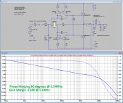
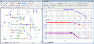
When plotting the loopgain with Tian's algorithm, overall stability is as good as it can be, but the oscillations between 15Mhz and 25Mhz are caused internally by the loop through the current mirrors and back to the opamp's output.
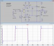
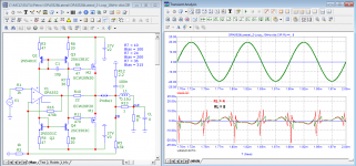
When using a 10Khz signal as you did with 1usec rise and fall time, LTSpice gives the response as below with re 10nF and 1uF // 8R.
Hans
When using a 10Khz signal as you did with 1usec rise and fall time, LTSpice gives the response as below with re 10nF and 1uF // 8R.
Hans
Attachments
With the BD/DH darlington configuration, the caps between the current sources work well too. Even R5 can be set to zero in sims and omitted in practice. The use in a sim is that it shows the switching issue of the AB power stage (shows well using IRF mosfet series). It would be interesting to know the improvement of 2SK1530/2SJ201 (not in uC lib) over the ECW series. Anyhow it's good to see the topology is useful.
Hans Polak, show distortion 10 kHz 20 Vpk at the output of the notch filterWhen plotting the loopgain with Tian's algorithm, overall stability is as good as it can be, but the oscillations between 15Mhz and 25Mhz are caused internally by the loop through the current mirrors and back to the opamp's output.
When using a 10Khz signal as you did with 1usec rise and fall time, LTSpice gives the response as below with re 10nF and 1uF // 8R.
Hans
best regards
Petr
Attachments
I assume you want to place a single 10Khz notch filter on a 10Khz square wave signal, that’s quite hilarious.
I’m afraid that vector errors will be convoluted with speed errors resulting in massive GD distortion.
Hans
I’m afraid that vector errors will be convoluted with speed errors resulting in massive GD distortion.
Hans
Completely lost in simulation land... get real. Listen to some music. Chill... ;-)Hans Polak, show distortion 10 kHz 20 Vpk at the output of the notch filter
best regards
Petr
//
Hans, we are talking about a sinusoidal signal. I have never tested square wave with this filter.I assume you want to place a single 10Khz notch filter on a 10Khz square wave signal, that’s quite hilarious.
I’m afraid that vector errors will be convoluted with speed errors resulting in massive GD distortion.
Hans
Petr
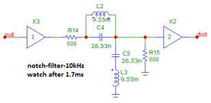
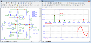
Just to show that you are chasing ghosts, I applied a 10Khz 20V peak signal to your LINEAR notch filter.
Since a linear filter doesn't produce distortion, this might be an opener for you.
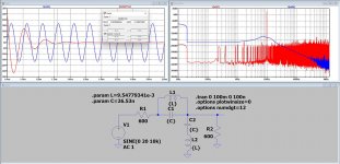
The time signal in red and the output signal in blue, shown at the left plot, reveals that after 1.3msec output ringing, caused by the abrupt starting 10Khz burst, becomes below 1usec, that's it, nothing further to discover.
The spectrum shows that the output signal is completely free of harmonics as a prove that linear filters don't distort, so this discussion also closed.
Hans
Since a linear filter doesn't produce distortion, this might be an opener for you.
The time signal in red and the output signal in blue, shown at the left plot, reveals that after 1.3msec output ringing, caused by the abrupt starting 10Khz burst, becomes below 1usec, that's it, nothing further to discover.
The spectrum shows that the output signal is completely free of harmonics as a prove that linear filters don't distort, so this discussion also closed.
Hans
Attachments
Hans, you're evading the answer again. Instead of showing what a composite amplifier adds at 10kHz with an output voltage of 20V(pic), you are demonstrating how a notch filter works. His work is shown in Fig. 5:Just to show that you are chasing ghosts, I applied a 10Khz 20V peak signal to your LINEAR notch filter.
Since a linear filter doesn't produce distortion, this might be an opener for you.
https://www.diyaudio.com/community/threads/musings-on-amp-design-a-thread-split.366099/post-7277148
Evading an answer and again, wow.
Why don’t you finally start by admitting that a linear filter doesn’t produce distortion.
All your theories are built on this misunderstanding. This has to be your first step before making any next step,
Simply confirm this with a yes and we can go on using an amp instead of voltage source.
Hans
Why don’t you finally start by admitting that a linear filter doesn’t produce distortion.
All your theories are built on this misunderstanding. This has to be your first step before making any next step,
Simply confirm this with a yes and we can go on using an amp instead of voltage source.
Hans
Hans, a linear filter doesn't add distortion, it measures it. Is it really incomprehensible? Look at the article frequency response graph of this filter. The filter suppresses the fundamental harmonic with a frequency of 10 kHz and passes harmonics from the second onwards 1:1.Evading an answer and again, wow.
Why don’t you finally start by admitting that a linear filter doesn’t produce distortion.
All your theories are built on this misunderstanding. This has to be your first step before making any next step,
Simply confirm this with a yes and we can go on using an amp instead of voltage source.
Hans
It's easier to type the model yourself and see how it works than to ask you to do something, just like and Bernhard.
For the amplifier model, the transistor models corrected by Bob Cordell are used.
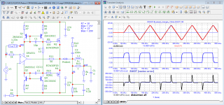
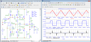
The first two graphs are what I asked Bernhard to do.
The third graph is the result of the test using a notch filter.
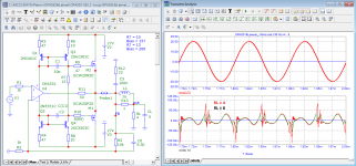
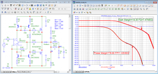
The fourth graph is the result of the test with a triangular signal.
Petr
p.s.
Parameters can be improved by using a different chip
Attachments
-
 04_OPA551&Lateral_10kHz-triangle_SWDT.png37.3 KB · Views: 139
 -
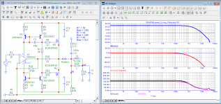
 03_OPA551&Lateral_10kHz-dist.png36.2 KB · Views: 126
 -
 02_OPA551&Lateral_Loop-Gain.png35.2 KB · Views: 143
 -
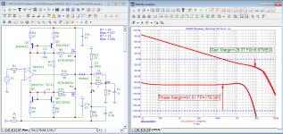
 01_OPA551&Lateral_Bode.png33.2 KB · Views: 133
 -
 01_OPA552&Lateral_Bode.png33.1 KB · Views: 118
 -
 02_OPA552&Lateral_Loop-Gain.png36.5 KB · Views: 128
 -
 03_OPA552&Lateral_10kHz-dist.png35.9 KB · Views: 120
 -
 04_OPA552&Lateral_10kHz-triangle_SWDT.png37.3 KB · Views: 121
 -
 05_OPA552&Lateral_20kHz-spectr.png33.1 KB · Views: 126
Last edited:

O.K. There it is, your final confirmation that linear filters don't distort, this is a big step forward, because it eliminates the existence of "Vector" and "Speed" errors.
I suppose that with "measuring" you mean processing the incoming signal with the filter curve.
First and second image:
Opposite to what Aridace and Tombo did, you increased gain by a factor 10, making your curves incomparable with theirs, but anyhow be aware its just a new situation and what you are showing seems to be correct.
The third image:
Yes this image shows the real distortion after notching out the main frequency, very informative showing (rather harmless) H2 and (to be avoided) crossover distortion.
The fourth image:
Showing meaningless "Vector" errors and "Distortion all", the latter by subtracting a time delayed and gain multiplied input signal from the output signal.
What has been mentioned more than once, you use only one single time delay that is stable up to ca. 20Khz, but beyond 20Khz the time delay is changing, causing that you make a large time delay error for frequencies above 20kHz.
Look at your "Distortion all" curve and you will notice risetimes of at least 2,5usec, corresponding to a frequency of ca 1.5Mhz. where GD is no longer 1.2usec but a factor 10 times less, thus causing a huge error in your subtraction plot.
So, "Distortion all" just as "Speed errors" are meaningless plots having no relation to real distortion.
The only correct plot in this series showing distortion is the third image.
Hans
P.S. In posting #997 I have shown that linear filters, where we have now agreed that the don't distort, are showing what you call "Speed Errors".
But since there cannot be any distortion in that case, there are no errors or distortions.
That is the easiest way to see that Speed errors don't exist.
Last edited:
P.S. In posting #997 I have shown that linear filters, where we have now agreed that the don't distort, are showing what you call "Speed Errors".
But since there cannot be any distortion in that case, there are no errors or distortions.
That is the easiest way to see that Speed errors don't exist.
Hans, if you want to understand what high-speed distortions are, carefully re-read the material that I posted.
I repeat once again, the notch filter can only highlight what the amplifier added to the sinusoidal signal in steady state: harmonics, switching distortion. No wonder we look after 17 periods of the signal, so you yourself saw it is useless to watch before 13 periods. Any THD meter works the same way!
The notch filter cannot pick out what the real signal is losing. After all, the real signal is more like a pulse signal than a sinusoidal one. Negative feedback works by comparing the input signal with the delayed signal from the output of the amplifier.
The subtraction of the input and delayed sinusoidal signals from the output of the amplifier does not lead to additional distortion, since there is always a tail of the sinusoid of the previous period. There is no such tail in real signals! - this is what we see at the beginning and end of the burst, with changes in the amplitude of the signal, with changes in its frequency, at the tops of the triangular signal.
Only the compensation method of measuring distortion allows you to measure what the signal loses. Losses of a signal also are high-speed distortions (losses).
I'm sorry to have to chew this up again.
Petr
Petr, this is utter nonsense.
How many times did I explain that your burst condition: sudden amplitude change in infinite short time, does not exist in audio real world because the music signal passes multiple lowpass filters before it reaches the power amp.
That information in the music signal which you claim to be be lost by the feedback delay, it is just not there.
ClassB crossover distortion is most probably a different thing because it happens inside.
But that doesn‘t bother me.
My last post on this topic.
Last edited:
Thus you have signed your helplessness to understand the essence of the compensation method for measuring distortionsO.K. after so many attempts I give up, you are not even sensitive to simple facts.
I wish you all the best in your self created high-speed bubble.
Hans
- Home
- Amplifiers
- Solid State
- Musings on amp design... a thread split