Simulators use sinusoidal signals to measure distortion. At the output of the tested amplifier models, distortions are added in the form of harmonic components that are multiples of the fundamental frequency: 2f, 3f, 4f, 5f, ....nf.
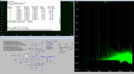
The 9th version of Micro-Cap is completely self-sufficient and largely automated, the levels of harmonic components (IHD) are displayed in% by default, as is customary to give in the specifications.
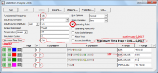
To measure the distortion spectrum, it is enough to leave lines 2 and 4.
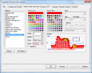
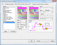
The settings for displaying on a chart are given in the properties windows.
The total THD at a frequency of 1 kHz is of little interest to me personally, it is much more important to look at the distribution of spectral components at least up to the 10th harmonic.
To see the dependence of the spectrum on the output voltage level, it is enough to set the input voltage in the stepping mode.
To see the dependence of the spectrum on the load impedance, it is enough to set the limits of load change in the stepping mode.
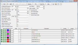
To display the spectrum of harmonics in the 12th version, you have to enter an additional line for IHD.
Using a few additional lines, you can see the spectrum in a stretched form.
best regards
Petr
The 9th version of Micro-Cap is completely self-sufficient and largely automated, the levels of harmonic components (IHD) are displayed in% by default, as is customary to give in the specifications.
To measure the distortion spectrum, it is enough to leave lines 2 and 4.
The settings for displaying on a chart are given in the properties windows.
The total THD at a frequency of 1 kHz is of little interest to me personally, it is much more important to look at the distribution of spectral components at least up to the 10th harmonic.
To see the dependence of the spectrum on the output voltage level, it is enough to set the input voltage in the stepping mode.
To see the dependence of the spectrum on the load impedance, it is enough to set the limits of load change in the stepping mode.
To display the spectrum of harmonics in the 12th version, you have to enter an additional line for IHD.
Using a few additional lines, you can see the spectrum in a stretched form.
best regards
Petr
Attachments
Last edited:
LOL
How do you generate that 10 kHz burst to test your amplifier ? Not in sim. In real world.
Let me guess... No answer. As expected.
Bernhard, I hope you are satisfied with this answer about bursts?
https://www.diyaudio.com/community/threads/musings-on-amp-design-a-thread-split.366099/post-7277214
Well, now it's your turn, finally present the Bode and loop gain plots. Alnikst even told you how to do it.
Otherwise, it is not clear why you came to this thread, maybe you wanted to say something? Dialogue fails. LOL - this is not a dialogue. There are plenty of laughers like that even without you.
")
best regards
Petr
Y
Hans
Just another tip: While carefully keeping the Bias current the same, I used 250mA, you can gain another 6dB as well in THD as in IMD by increasing the four current mirror resistors a factor five to resp. 232R and 50R when running the 950Hz+11.5Khz IMD test both at 4.5Volt input.MJH6284 and 6287 are about the worst choice for a darlington. So I also ran a sim with a combination resembling STD03N and STD03P at ~ 100 mA Quiescent current.
Hans
No.Bernhard, I hope you are satisfied with this answer about bursts?
Remember: First you came up with the AP that has only 96 kHz, far from your infinity.
Look at the specs of your 12 bit Agilent.
Where is the infinite bandwidth?
And where does the infinite bandwidth? instead of answering the questions that you are asked (Bode plot and loop gain plot), you once again drive diarrhea of wordsNo.
Remember: First you came up with the AP that has only 96 kHz, far from your infinity.
Look at the specs of your 12 bit Agilent.
Where is the infinite bandwidth?
it makes no sense to keep talking with you, then I just ignore
Learn to use the microcap. Until I saw that you learned to use it as a tool
best regads
Petr
Last edited:
Good point, usually distortion is optimized for max power although that is rarely used. Hence I also have been working at still simpler applications, like a dual opamp directly driving that STD03-like darlington configuration, also at ~250 mA. In my case, about 40 W (4 ohm) still is more than enough and the IMD behavior is even better.Y
Just another tip: While carefully keeping the Bias current the same, I used 250mA, you can gain another 6dB as well in THD as in IMD by increasing the four current mirror resistors a factor five to resp. 232R and 50R when running the 950Hz+11.5Khz IMD test both at 4.5Volt input.
Hans
Alexander Petrov, in my country there is an apt saying for your pathetic behavior.
“Seeing that horses are shoed, frog lifted its leg.”
As your understanding of anything is feeble, no, I’m not calling you a horse or a frog.
In my country, they learn from such gurus as Lamm, Charles Hansen, John Curl, Nelson Pass and similar world luminaries and do not laugh if they do not understand something.
For "laughter for no reason is a sign of a fool"
@Aridace
Amplifier topology from post #1147 yields great results in simulations. Even with LTSpice, if output stage operates in A class, I can get several ppb distortion just before clipping. Result is 60 dB better than using the same components in standard composite amplifier topology. In simulation, amplifier is stable without C6, C7 and C11.
As my amplifier at the bench was output stage enclosed in opamp feedback, it was not too hard to rearrange components on the breadboard.
What I was afraid of, happened. Amplifier is very unstable and oscillates even with very large C10 (330p) and C11 as specified. Though, I used noninverting configuration but that shouldn’t matter.
I don’t see a point in endless chasing of low distortion numbers with just theoretical topology, not confirmed in practice. It may work with some tweaking but that can be done only in practice.
Those same components, arranged as a classic composite amplifier, provide rock stable performance with any capacitive load, 1.7 MHz power bandwidth, 200 ns rise time and distortion in range of -110 to -130 dB (full power/1W). I would very like your topology to work stable but if not, what I have is acceptable as well.
Attachments
Did you also use the 3k and 1k5 feedback resistors with the OPA552 ?
Miminum (noise) gain should be 5 so instead of 1k5 use a 600R resistor.
Or you could as Aridace did split the 1k5 in 900R and 600R and connect a cap in between to increase high frequency noise gain to 5.
Hans
Miminum (noise) gain should be 5 so instead of 1k5 use a 600R resistor.
Or you could as Aridace did split the 1k5 in 900R and 600R and connect a cap in between to increase high frequency noise gain to 5.
Hans
When you create signal generator in a simulator to simulate a DUT, you should also place a LP filter on the output of said generator in order to represent a situation as it would appear in reality - otherwise you will have a pulse start that is not possible in the real world and hence, a non valid simulation. You decide what the filter fo should be and of course describe why the choose value was selected.
//
//
@tombo56 Addicted to easy going, my habit was to apply ECW laterals in about every final stage, as distortion is low enough and temperate stability a nonissue. It's true that class A is superior but here, with too frequent power cuts and generators breaking down (then using the car for power generation, just 200W), class AB with distortion "low enough" ( = sim THD 1k, (950, 11.5k 1:1 below -140 dB ) is the safer option. So I investigated many topologies. Running transient analysis at 1n or less, I discovered quite a few parasitic oscillations in cases where stability was OK. Knowing from experience how difficult it is to produce an analogue device with dynamic range >140 dB, I aim at a sim, some 20 dB better. BTW most of my simmed contraptions can be seen as nested feedback loops which implies that when constructing, the main loop gets measured first, eventually optimized / corrected, next follows the other loop(s).
It's true that class A is superior but here, with too frequent power cuts and generators breaking down (then using the car for power generation, just 200W), class AB with distortion "low enough" ( = sim THD 1k, (950, 11.5k 1:1 below -140 dB ) is the safer option.
I gave OPA551 a chance. Result is the same. Only difference is that oscillation frequency is lower. Changing C10 only alters oscillation frequency but not amplitude (some 4Vpp). It would need careful tweaking.
Good to know. I only stocked up on OPA 552 because at the time of ordering the issue reminded of what I experienced long ago with LF356 / 357. In applications aimed at maximum performance I always used 357, compensating as required (but often different from app note), in the other applications, 156.
It's more than likely the amp with dual LME49680 would require tweaking too but it's only once.

It's more than likely the amp with dual LME49680 would require tweaking too but it's only once.
I noticed that the circuit is sensitive to oscillations for loads higher as 4R.
I gave OPA551 a chance. Result is the same. Only difference is that oscillation frequency is lower. Changing C10 only alters oscillation frequency but not amplitude (some 4Vpp). It would need careful tweaking.
When changing the resistor at the output of the OPA551 to 150R and inserting two 10pF caps between the collectors of the two current mirrors, stability should be there for all loads.
Hans
- Home
- Amplifiers
- Solid State
- Musings on amp design... a thread split