I am building a 71A preamp, but really struggling with the microphonics, despite all the usual countermeasures. I might switch to a 2P29L since I can reuse all of the other elements I already have in place. I'll have to change a few of the operating points of course, but will be pretty easy.
But this tube is too much gain for me.
I know its a total taboo, but how might I add 10dB of local feedback? Is that crazy? I would be using a circuit similar to Ale's but with a 10m45s CCS on top rather than his gyrator.
https://www.bartola.co.uk/valves/2017/05/20/2p29l-dht-preamp/
I'm aware that I can just voltage divide the output down as he did here, but I already have a 100K stepped attenuator wired to the output so trying to stick with that.
I know my suggestion might be heresy, but willing to take one for the team and try it out. Just need a little help with the schematic. Thanks!
Try a 112A. Not quite so much gain as a 2P29L and sounds better. Filaments should be the same.
Or use a 2a3 or 6B4G - they make good small tube stages as well as outputs. I had a 6C4C Svetlana stage that sounded very good. Detailed and dynamic.
Or use a 2a3 or 6B4G - they make good small tube stages as well as outputs. I had a 6C4C Svetlana stage that sounded very good. Detailed and dynamic.
The 112A is logical cousin to the 71A, but not sure it will be any better microphonically. From what I understand this little 2P29L is not microphonic at all. And cheap!
So just exploring the feasibility of applying some feedback. I haven't seen anyone do it, so always exploring the road less traveled. We work hard to get the filaments quiet, and to get everything such noise, then throw it away with a noise floor that's bouncing around 30dB due to microphonics. I can convince myself I can't hear it that much, but it's not a pretty site on the analyzer. Also, I don't like having to relocate the amplifier away from the speakers so much.
So just exploring the feasibility of applying some feedback. I haven't seen anyone do it, so always exploring the road less traveled. We work hard to get the filaments quiet, and to get everything such noise, then throw it away with a noise floor that's bouncing around 30dB due to microphonics. I can convince myself I can't hear it that much, but it's not a pretty site on the analyzer. Also, I don't like having to relocate the amplifier away from the speakers so much.
Last edited:
I am building a 71A preamp, but really struggling with the microphonics, despite all the usual countermeasures. I might switch to a 2P29L . . . But this tube is too much gain for me.
I'm aware that I can just voltage divide the output down as he did here, but I already have a 100K stepped attenuator wired to the output so trying to stick with that.
Looks like the 71A has a mu of 3 so there's probably not many tubes with a mu that low. As I recall, the 2P29L has a mu of ~8.The 112A is logical cousin to the 71A, but not sure it will be any better microphonically. From what I understand this little 2P29L is not microphonic at all. And cheap!
So just exploring the feasibility of applying some feedback. . . . I can convince myself I can't hear it that much, but it's not a pretty site on the analyzer. Also, I don't like having to relocate the amplifier away from the speakers so much.
When I had it breadboarded it certainly didn't seem to have all that much gain, but this is totally based on what I was hearing, not on theory / measurements. Have you tried the 2P29L and listened or are you basing your concerns about too much gain on the data sheet. Looks like the 12A is about the same at mu 8.5, BTW.
The preamp I ended up building uses the 1626, which has a mu of 5. It's not directly heated, though, if that's a requirement.
I also use a stepped attenuator on the output but, in addition, I have a pair of mono pots on the input, which are mainly used as a balance control. So that's another option.
Another possible solution . . . I know Andy has been using some Hammond 1140-LN-C input transformers that are wired in reverse to produce a step-up. You could use them, or something similar, as intended to create a step down. I picked up some too but haven't used them yet.
Yes, the Hammond 1140-LN-C are very good and very good value. They come in front of my 10Y stage, which is the driver for my 2a3 outputs.Another possible solution . . . I know Andy has been using some Hammond 1140-LN-C input transformers that are wired in reverse to produce a step-up. You could use them, or something similar, as intended to create a step down. I picked up some too but haven't used them yet.
But seriously, for low mu do try the 6B4G or 6C4C. It sounds great. I used Rod Coleman regs and his V9 is the best yet. Very good value too.

Yes, I could certainly attenuate the input as well. Trying to explore some uncovered ground is all. Not a firm believer feedback is bad, and also experimenting is really the only way I know how to learn.
I'm not very technically astute, but I've always considered gain reduction to be a side effect of negative feedback, not a primary reason to use it.Yes, I could certainly attenuate the input as well. Trying to explore some uncovered ground is all. Not a firm believer feedback is bad, and also experimenting is really the only way I know how to learn.
Is the additional gain actually causing any problems, such as severely limiting the usable range of the volume control?
Nothing wrong with killing 2 birds with one stone and experimenting and learning in the process. Yes decreasing gain is a usable side effect, but curious about linearizing a bit more and also reducing microphony and negative feedback would help. Microphonics has been the real eye opener with this DHT journey so far.
Yes I know maximizing SNR by attenuating at the end also has that effect also.
There seems to be a lot of myths in audio. I’d rather build, measure, listen and try something new, that’s all
Yes I know maximizing SNR by attenuating at the end also has that effect also.
There seems to be a lot of myths in audio. I’d rather build, measure, listen and try something new, that’s all
Absolutely, nothing wrong with experimenting.Nothing wrong with killing 2 birds with one stone and experimenting and learning in the process. Yes decreasing gain is a usable side effect, but curious about linearizing a bit more and also reducing microphony and negative feedback would help. Microphonics has been the real eye opener with this DHT journey so far.
Yes I know maximizing SNR by attenuating at the end also has that effect also.
There seems to be a lot of myths in audio. I’d rather build, measure, listen and try something new, that’s all
But triodes, especially DH ones, tend to be quite linear. When negative feedback is used to linearize, it's typically with pentodes, which are not so linear on their own. Perhaps others with more technical expertise will correct me if I'm misunderstanding this, but I can't imagine that it would result in any more linearity than a nice DHT already has.
And I don't think feedback will affect microphonics either, unless the amount used results in a drastic reduction in gain. Obviously, you don't need to reduce gain if you stick with the 71A. And if you switch to the 2P29L, you won't have a problem with microphonics.
I avoided using DH tubes for years because of all the talk about hum and microphonics but those issues have been far less problematic than I expected. Never tried the 71A but I'm using the 26 (which also has a reputation for being problematic) in my most recent amp build and haven't had any functional issues. And I've taken no unusual steps at all with the tubes, they're treated just like an indirectly heated tube except for using basic DC on the filaments.
Try feedback if you like but I'm guessing that adding enough feedback to reduce the gain as much as you want will likely result in a very dull sounding preamp.
Earlier, I asked: Have you tried the 2P29L and listened or are you basing your concerns about too much gain on the data sheet? I suggest you listen first.
You're only talking about going from a mu of 3 to a mu of ~8. You're not switching to 12AX7s which have a mu of 100.
As I see it, unless the additional gain severely limits the usable range of the volume control there is no problem to solve.
I'm not even sure how you would implement NFB in a preamp. I've always seen FB taken from the secondary of an output transformer or from the plate of the following tube. The schematic you linked earlier has neither. Can it simply be taken from the output?
The only method I'm aware of that adds NFB and reduces gain in a single tube is to use an unbypassed cathode resistor.
You can apply parallel (shunt) negative feedback from the output (plate or anode) to the grid of a triode.
Some call that an 'anode follower', but that is a confusing name.
https://www.tubecad.com/2019/03/blog0458.htm
Hi Charlie,
I will try this tube and compare it against the 71a. So we’ll see! I’ll also present some measurements and listening impressions, so it will be quite interesting!
As for feedback, I think this becomes an academic and unnecessarily ideological debate, although I admire your fervency and plea to not try feedback. In the end maybe I won’t, but after all there are only 2 resistors. So easy to try, what’s the harm? Try and listen both ways.
I think the elephant in the room is microphonics. Without measurements some have concluded they have have solved the problem. Maybe they’ve suppressed it below -80dB so cannot hear it, but let’s opine about how running smps on a filament will induce intermodulation distortion at -110 dB/V lol. That’s not directed at you, but I find some of these conversations rather amusing
The other problem of ancient DH tubes not only microphonics, but tend to sensitivity of magnetic and/or electric field (EMF).
Some tube (same type, different manufacturer and/or different production time) insensitive, some has horrible behaviour.
Decade ago I measured few dozen of #26 tubes, only few was insensitive of EMF.
The biggest difference (at 50Hz component) between tubes was 40db!
The other ones are good tubes, but was necessary to shield its (aluminium or permalloy folie).
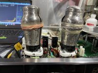
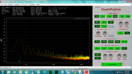
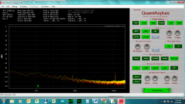
Yes, indeed true! Look at the difference with the tubes shielded vs not. Almost 40db difference at 60hz, plus all the other noise. The left channel on the one attachment I removed the shield. The other attachment is with both tubes shielded.
That’s why I’ve come around to these 2P29L tubes. Reputation for not being microphonic, plus they’re already shielded with their dorky but kind of cute hat. I kinda like how they look- others may disagree
That’s why I’ve come around to these 2P29L tubes. Reputation for not being microphonic, plus they’re already shielded with their dorky but kind of cute hat. I kinda like how they look- others may disagree
Attachments
Last edited:
I must be one of the confused.You can apply parallel (shunt) negative feedback from the output (plate or anode) to the grid of a triode.
Some call that an 'anode follower', but that is a confusing name.
https://www.tubecad.com/2019/03/blog0458.htm
View attachment 1117962
View attachment 1117963
I always thought the term "anode follower" referred to the first circuit, which uses a single tube (or section) simply because the output is taken from the anode. Whether or not feedback is involved.
I thought the lower circuit was called a cathode follower, because the output is taken from the cathode of the second tube. Again, independent of any feedback arrangement.
I'll have to take a look at the link.
I agree, try it. I'm not anti-feedback, I've used it in various builds.Hi Charlie,
I will try this tube and compare it against the 71a. So we’ll see! I’ll also present some measurements and listening impressions, so it will be quite interesting!
As for feedback, I think this becomes an academic and unnecessarily ideological debate, although I admire your fervency and plea to not try feedback. In the end maybe I won’t, but after all there are only 2 resistors. So easy to try, what’s the harm? Try and listen both ways.
I didn't really mean to discourage you from trying, I just don't think it will solve your "gain problem" without negatively affecting the sound. But, from a practical standpoint, I don't really think you actually have a gain problem, which is why I asked about how it was manifesting itself, whether functionally or audibly.
You didn't respond so apparently your concerns are totally theoretical.
Your comment certainly applies to me but I take no offense.I think the elephant in the room is microphonics. Without measurements some have concluded they have have solved the problem. Maybe they’ve suppressed it below -80dB so cannot hear it, but let’s opine about how running smps on a filament will induce intermodulation distortion at -110 dB/V lol. That’s not directed at you, but I find some of these conversations rather amusing
I know that most who post on here are all about measurements and their goal is engineering perfection. It's more of a pure science approach. Nothing wrong with that.
I'm just a hobbyist who loves music and my approach is totally practical. Bottom line, audio gear is made to be listened to.
If measurement tools can be effectively used to improve the audible results I'm all for it. But if technical changes don't improve the sound that I hear I don't consider them to be successful from a practical standpoint. I really couldn't care less if something measures better if there is no audible benefit. While I can appreciate the technical aspects, I consider practical, audible, results to be far more important.
I build stuff to listen to it. Listening to music gives me pleasure. I get no pleasure from the measurement process or viewing the results. Solving inaudible "problems" is not something that I find satisfying.
No doubt the more scientific types here get great pleasure and satisfaction knowing that something they tried measures better even though it can't be heard. That's fine, too.
For me, the measurements is just a tool to help pinpoint what it is I'm hearing. For example, something might be noisy. Where noisy? Is it 50/60Hz, 100/120Hz or some harmonic, or is broad base high noise floor. Or is it high frequency hash? If so is it spikey, or centered on one frequency?
If it sounds too rounded, what's the harmonic profile? Maybe I can explore different operating points.
It's not about engineering perfection.
With the microphonics issue, I was hearing some haziness with complex music. Couldn't quite put my finger on it. So seeing a bunch of noise hopping around from -100 to -50dB provided some clues.
As to the gain question, I'm running the preamp into a solid state amplifier that has 20dB of gain already, so really aiming for a 6-10dB to give some headroom and explore playing with these ancient tubes. Anything above 12V output into the power amp is inadvisable and likely to cause damage. I have a pot on the output of the preamp so that's helpful, but I think good design is not have any case where catastrophic failure is possible.
Speaking of ancient tubes, and back to the 2p29L, does anyone have any information as to the history of this tube? Looks like it was introduced back in 1938. And in these interesting devices:
https://www.radiomuseum.org/tubes/tube_2p29l.html
https://www.radiomuseum.org/r/military_funkstation_r_106_p_106.html
https://www.radiomuseum.org/r/videoton_hordozhato_urh_ado_vev_portable_fm_transceiver_r.html

I must be one of the confused.
I always thought the term "anode follower" referred to the first circuit, which uses a single tube (or section) simply because the output is taken from the anode. Whether or not feedback is involved.
I thought the lower circuit was called a cathode follower, because the output is taken from the cathode of the second tube. Again, independent of any feedback arrangement.
I'll have to take a look at the link.
When you have the more common plate-loaded triode amplifier stage like this:
Circuit 1:
That is most properly called a "common cathode amplifier", because the cathode is grounded (common).
An "anode follower" can also be called an "inverting amplifier", which is simply the above common cathode amplifier with shunt feedback taken from the plate and applied back to the grid:
Circuit 2:
To make that 'anode follower' or 'inverting amplifier' work better driving both the load and its negative feedback loop, you can buffer its output with a cathode follower. That doesn't make it a different amplifier, really. It makes it a buffered inverting amplifier:
Circuit 3:
Circuit 1 is a common cathode amplifier.
Circuit 2 is a simple anode follower (aka inverting amplifier).
Circuit 3 is a buffered anode follower (aka buffered inverting amplifier).
Basically, the only real difference between Circuit 2 and Circuit 3 is that Circuit 2 is an anode follower in isolation, while Circuit 3 is an anode follower with a cathode follower added to make it work better.
It's a little hard to explain in words, but I think that gets the idea across.
Last edited:
Circuit 1 , common cathode amplifier also inverts phase on output so term "inverting amplifier" applyes also. 🙂
I don't know why the names are what they are.
Add shunt feedback to make Circuit 2 and you have a Common Cathode Amplifier with Shunt Feedback. But that's a lot of words.
I always thought Circuit 2 was named an Anode Follower.
Here's an old article that calls it an anode follower: https://www.aikenamps.com/images/Documents/anode.pdf
I think that's because you can apply enough NFB so that it has a gain of 1, making it a 'follower' but the output signal comes from the plate, so it's not a cathode follower.
Then I saw in Morgan Jones "Valve Amplifiers" that he called it an Inverting Amplifier or just "inverter".
I think some call Circuit 2 an inverting amplifier following common practice for opamps. On that page, notice that the Op-amp Inverter is the same thing as the triode anode follower.

I don't think Circuit 3 has a commonly accepted name. In the Anode Follower article above, the author calls it an "Amplifier with extremely low output impedance."

True. But common usage is to call Circuit 1 a Common Cathode Amplifier.Circuit 1 , common cathode amplifier also inverts phase on output so term "inverting amplifier" applyes also. 🙂
Add shunt feedback to make Circuit 2 and you have a Common Cathode Amplifier with Shunt Feedback. But that's a lot of words.
I always thought Circuit 2 was named an Anode Follower.
Here's an old article that calls it an anode follower: https://www.aikenamps.com/images/Documents/anode.pdf
I think that's because you can apply enough NFB so that it has a gain of 1, making it a 'follower' but the output signal comes from the plate, so it's not a cathode follower.
Then I saw in Morgan Jones "Valve Amplifiers" that he called it an Inverting Amplifier or just "inverter".
I think some call Circuit 2 an inverting amplifier following common practice for opamps. On that page, notice that the Op-amp Inverter is the same thing as the triode anode follower.
I don't think Circuit 3 has a commonly accepted name. In the Anode Follower article above, the author calls it an "Amplifier with extremely low output impedance."
Last edited:
- Home
- Amplifiers
- Tubes / Valves
- 2P29L Preamp