I know one good boyzMy Google-Fu / diyA search skills are lacking. I think (but I can't find it to provide a link nor do I remember the specifics) that someone implemented a DVM readout and some front-panel mounted pots for easier alteration of their H2V2.
I dig it.

Hello all,
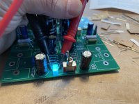
I have the ACA Mini board but had to source the parts myself as kits were sold out at the time of my order. I did not see any insulater pads for the transistors. The photo by 6L6 appears to apply only heatsink grease. Is the grease all that is required or should a mica or other pad be used? Thank you.
I have the ACA Mini board but had to source the parts myself as kits were sold out at the time of my order. I did not see any insulater pads for the transistors. The photo by 6L6 appears to apply only heatsink grease. Is the grease all that is required or should a mica or other pad be used? Thank you.
Insulators are not required if you use the PCB mount heatsinks. (They certainly won't hurt if you hav some.)
If you mount the transistors to another surface insulators are required.
If you mount the transistors to another surface insulators are required.
I used a tiny dab of grease on each FET. The heatsinks seem very effective. It takes about 10-15 minutes for the amp to fully warm up. If in doubt I would use the grease. Most people over apply it. It really only takes a little dab in the center of the FET.Hello all,
I have the ACA Mini board but had to source the parts myself as kits were sold out at the time of my order. I did not see any insulater pads for the transistors. The photo by 6L6 appears to apply only heatsink grease. Is the grease all that is required or should a mica or other pad be used? Thank you.
Has anyone bridged a pair of ACA minis? Is it possible? if so how?

I did it and it works well. I used a simple unity gain inverter circuit with a TL071 to feed the negative side. But, you could probably use a resistor to tap the inverted signal from the drain of Q1. It looks like there is a symmetric inverted signal there. But... I have not tried it and I'm not sure what effect that would have on the bias. Considering it would be driving a 100k load plus divider resistor I'm thinking it could workHas anyone bridged a pair of ACA minis? Is it possible? if so how?
View attachment 1105800
This is what I did with a TL071 and it works well. Unity gain stable and FET (Hi Z) input were the reasons I chose this part.I did it and it works well. I used a simple unity gain inverter circuit with a TL071 to feed the negative side. But, you could probably use a resistor to tap the inverted signal from the drain of Q1. It looks like there is a symmetric inverted signal there. But... I have not tried it and I'm not sure what effect that would have on the bias. Considering it would be driving a 100k load plus divider resistor I'm thinking it could work
Someone smarter than me could probably figure out something better.
Absolutely. I also put a balanced XLR in my amps but I have no balanced source to try it with. Some people say gimmick, some say problem solved. 😎fed it with balanced signal, there is bridging without gimmicks
Absolutely. I also put a balanced XLR in my amps but I have no balanced source to try it with. Some people say gimmick, some say problem solved. 😎
plenty of ways to ...... paint the Fence
SE/Bal xformer
OP inverter
in this case you can't use same trick as with ACA; feeding one "phase" output to other "phase input" is possible only if "phase" (previously channel of normal stereo amp) is inverting signal (output vs. input)
Bal+ to right channel hot lead. Bal- to left channel hot lead. Bal gnd to Mini gnd. Connect speaker + to Right + and speaker- to Left +.Would you guys mind letting us know how exactly you wired the balanced input to the amp?
I was naively hoping that there was a simple way to connect the negative input to the sources of the input pair.plenty of ways to ...... paint the Fence
SE/Bal xformer
OP inverter
in this case you can't use same trick as with ACA; feeding one "phase" output to other "phase input" is possible only if "phase" (previously channel of normal stereo amp) is inverting signal (output vs. input)
There is. Re-read #1394I was naively hoping that there was a simple way to connect the negative input to the sources of the input pair.
Ah sorry, your reply arrived while I was typing 😉
But I meant something different: Connect the Bal- to the same input pair as the Bal+, thus still having a stereo amp with one board. Somewhere close to the feedback path, I was hoping.
But I meant something different: Connect the Bal- to the same input pair as the Bal+, thus still having a stereo amp with one board. Somewhere close to the feedback path, I was hoping.
you can try it
you'll get either silence ...... or buzz ...... or fireworks

in fact , I remember Lampizator Guru did some of his endeavors - connecting Bal signal to common anode triode stage; well, I know I'm dumb and I never understood how's that working
though, every lousy solution lacks just one element to became perfect solution - some amount of perfectly sold mythology ....... and there you have it - High End

(generally, you can feed one phase to gate, second phase to source, and you'll get some sort of balanced amplification, but so bad that it hurts ........ except in case that you're feeding both nodes with 0 Ohms of Rout; but in this case )
you'll get either silence ...... or buzz ...... or fireworks
in fact , I remember Lampizator Guru did some of his endeavors - connecting Bal signal to common anode triode stage; well, I know I'm dumb and I never understood how's that working
though, every lousy solution lacks just one element to became perfect solution - some amount of perfectly sold mythology ....... and there you have it - High End
(generally, you can feed one phase to gate, second phase to source, and you'll get some sort of balanced amplification, but so bad that it hurts ........ except in case that you're feeding both nodes with 0 Ohms of Rout; but in this case )
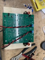
ACA mini is ready for action. I went to get a picture frame at the craft store, but ended up with this box for less than $6. Speaker posts and “ice blue” ice cube LED were in the parts box. Today I’ll test it on real speakers. It sounded great on my bench speakers. I may paint or oil the box at some point in the future.
Thanks Nelson for another cool project!!
Thanks Nelson for another cool project!!
Attachments
-
 C3397A3B-8CA1-4464-9411-1F061427EF7A.jpeg424.5 KB · Views: 259
 -
 BCCED86D-BC47-49FC-B630-D6E08FFC5B07.jpeg616.3 KB · Views: 242
 -
 F7CD4962-19B9-483B-AAF2-9704EE01D0F4.jpeg418.5 KB · Views: 244
 -
 75F7C195-EF06-4539-B7DD-2759AECE4F8D.jpeg484.1 KB · Views: 256
 -
 6DED1B9D-5299-46A7-B835-42964DAF039B.jpeg474.1 KB · Views: 267
I’ve had this amp playing a few hours today on 91dB JBL 4410 monitors. Wow. This is easily the best bargain in audio. It punches several levels above its weight. Well done on this kit design!!!
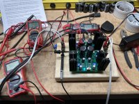
Just for kicks I put some FQP3P20/FQP2N30 in an ACA Mini. It biases up just fine, but the pots are set closer to the end of their travel (almost fully clockwise). I have not listened yet. I have a second ACA Mini with the Harris 520/9520 to compare. Should be interesting.
Here's what 1 watt output looks like on the spectrum analyzer:


Here's what 1 watt output looks like on the spectrum analyzer:
- Home
- Amplifiers
- Pass Labs
- DIY ACA mini