nope just switch ON the bias after smps if isn't poweredDo you suggest we replace the two resistors in our earlier ACA mini builds?
Thanks. But is the 200k r2 also part of that? If seems that would change the offset a tad, but not affect the bias cap charge rate much at all.Slower start up to accommodate switching supplies that balk at high turn on currents.

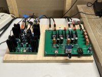
What a great pair. I’m loving how this combination sounds.
I’m using it with miro’s AD1862 DAC, Sony SS-CS5 speakers, and a Yamaha sub in a desktop setup.
I was using an Aiyima A07 amp with LM4562 opamps and the ACP+. The ACA mini just blows it away for me, i.e. more personal musical enjoyment.
I’m using it with miro’s AD1862 DAC, Sony SS-CS5 speakers, and a Yamaha sub in a desktop setup.
I was using an Aiyima A07 amp with LM4562 opamps and the ACP+. The ACA mini just blows it away for me, i.e. more personal musical enjoyment.
Attachments


Here is the updated BOM from Nelson that addresses the issues mentioned in his post #1216. It reflects the changes: R2 = 200K, and R4 = 22.1K. These changes have been incorporated in the new batch of completion kits that are about to hit the shelves.
I noticed that the 15K caps, C2 and C3, have been replaced by 10K caps in the updated BOM. Has this been discussed before, and if not, what is the reasoning? And while I am asking, I guess R4 = 20K would work as well?
It would shift the DC output a little, but the bias pots can adjust that if needed.Thanks. But is the 200k r2 also part of that? If seems that would change the offset a tad, but not affect the bias cap charge rate much at all.
I recall that there was a supply issue. The difference was judged to be trivial, as it's just a switching supply filter, and 10k is still overkill.I noticed that the 15K caps, C2 and C3, have been replaced by 10K caps in the updated BOM. Has this been discussed before, and if not, what is the reasoning? And while I am asking, I guess R4 = 20K would work as well?
Re: Supply issue,
It should be noted that, thanks to Nelson, the 100 completion kits just shipped to the store include the same NOS 15K Panasonic caps that were included in the first batch.
For subsequent batches it remains to be seen what can be sourced. This shipment arrived at the warehouse on Monday the 24th so they should be available soon. Get 'em while you can! If interested there's a link on the store's ACA Mini page that will allow you to be notified by email when they are in the system again.
Slower start up to accommodate switching supplies that balk at high turn on currents.
FWIW the SMPS that comes with the ACAmini store kit works just fine for my (stock) build. No problems on startup.nope just switch ON the bias after smps if isn't powered
The original circuit appears to have been on the edge of the issue which is why it occurred in some but not others with the later power supplies. If they start up, they're fine. If not, then you can turn the switch off and restart and they work. The larger resistor appears to take care of it by reducing the initial inrush of current on turn-on.
I was thinking about the startup issue this morning. If you recall we had a similar issue with the ACP+ kits a while back too. The culprit in both cases was the SMPS not liking the low input impedance of uncharged caps which triggered its "hiccup" short-circuit protection mode. I was wondering if it would be a more general solution to use a higher-ESR cap as the first cap (and perhaps the first R too) in the CRCRCRC input filter bank for any projects that are being designed to use a SMPS? That would provide enough R on the initial cap to let it start charging.The original circuit appears to have been on the edge of the issue which is why it occurred in some but not others with the later power supplies. If they start up, they're fine. If not, then you can turn the switch off and restart and they work. The larger resistor appears to take care of it by reducing the initial inrush of current on turn-on.
--Tom
just some second to charge caps ,so simpleI was thinking about the startup issue this morning. If you recall we had a similar issue with the ACP+ kits a while back too. The culprit in both cases was the SMPS not liking the low input impedance of uncharged caps which triggered its "hiccup" short-circuit protection mode. I was wondering if it would be a more general solution to use a higher-ESR cap as the first cap (and perhaps the first R too) in the CRCRCRC input filter bank for any projects that are being designed to use a SMPS? That would provide enough R on the initial cap to let it start charging.
--Tom
With the seasonal change in temperatures in my part of the world, I was able to capture how the bias voltage on the ACA Mini varies with room temperature. The plot below shows how, for one constant setting of the potentiometers, the bias changes as a function of ambient T. Measurements were only made at 3 temperatures (62°F, 65°F, and 69°F), but extrapolated a bit, assuming linear behavior.
The variation is not minor, and as Nelson Pass indicated earlier, bias is best set for the expected room temperature. It seems to me that that the need for seasonal adjustment should be anticipated.
Providing this with the hope that it is useful to others.

The variation is not minor, and as Nelson Pass indicated earlier, bias is best set for the expected room temperature. It seems to me that that the need for seasonal adjustment should be anticipated.
Providing this with the hope that it is useful to others.
^. Thanks for sharing! 🙂. Wonderful stuff. A ~33% measured increase from 62F (~30mV) to 69F (~40mV) is notable.
- Note - bias current units would be mA vs. mV. I assume your measurements noted on the chart were the DC voltages measured between the two pads labeled VB. If so, I think your bias current would be those measurements / 0R75. Not particularly relevant, and it doesn't diminish your work. Just an observation.
Edited to correct my sloppy math. 😉. Too early and not enough coffee.
Yes, I gave the bias values as mV across the Vb pads, as that is the way Pass intended bias to be monitored, and yes that corresponds to across R8 (0R75). Obviously a lot easier to measure that voltage than opening a connection to insert an ammeter.
The actual values were 29mV at 62°, 33mV at 65°, 38.5mV at 69°. Vo varied from 11.55V to 11.53V to 11.49V, respectively.
The bias at 69° was higher than I intended to run the ACA Mini at. It happened when our outside temps in southern New England rose to over 70° a couple of days ago, and the heat sinks felt hot, prompting me to check the bias. I also measured the temp of the sinks then, and they were at 50.3°C. I left all the settings alone, as I knew it was going to cool off the next day (and stay that way until Spring), and everything was behaving stably. In the heating season, the room varies between 62° (night) and 65° (day).
I remember those panel dials for multi-turn pots, with the revolution counter window and shaft locks on top, from analytical equipment I used to work with.
My Google-Fu / diyA search skills are lacking. I think (but I can't find it to provide a link nor do I remember the specifics) that someone implemented a DVM readout and some front-panel mounted pots for easier alteration of their H2V2.
I dig it.
I dig it.
- Home
- Amplifiers
- Pass Labs
- DIY ACA mini