You just repeated what I already said - about 2 side isolation of toe lanimation. Does not matter what shape of the lamnation until alloy is right ro the specific aplication. And off course windings space...All transformer laminations have a isolation on both side otherwise there is to much eddycurrent. EI i never want because of bad physical properties. EI is for cheap solutions.
cheers
This is not about undersizing core afainst neded power, in this example of iron core from the photos, the winding space almpst does not exixsts, it is for special purpose core capable to accept very small nuber of turns... 🙁If we shrink core area, the power can be delivered by core is also decreased. We can increase the winding room, but that will add more magnetic length, and more turns of primary.
By the way, the window area for winding is enough for me.
There are some first steps n the design process. Balancing parameters are not in the first steps area...When designing a transformer, it's important to focus on getting a balance of as many parameters as possible. And the recipe for this balance is up to you. Good or bad transformer, everyone has different preferences here. Deducted from this logic, I find defining a transformer as good or bad as obsolete.
In my cookbook, I start with the basic requested parameters. Primary impedance, impedance ratio, maximum power output per frequency, maximum permissible Rdc losses, inductance and Idc (SE). Then I select a core, interleaving, number of turns and check the leakage inductance. If the later is satisfactory, I sketch the interleaving, calculate and distribute capacitances. Capacitance distribution is important and is unique for specific projects (high, low Z OPT, step-ups, phase splitters).
First step is to chosse a core aloy and consider window space.
Impedance transformation ratio is certanly not first thing.
Your goal has to be
transfer BW with minimum phase shift, permeability of lamination core, Primary inductance, Leakage inductance, winding capacitances, and so
then minimum histeresis distortion - induction of primary, air gap, magnetic lines lenght,,,
...
If You from the start chose core material with inapropriate characteristics
Does not have the much point is there a transfer impedance ratio is good.
...🙁
Guess what?
You cannot guarantee "minimum phase shift" in the high-frequency region without taking acount the transformer impedance ratio first. The impedance ratio will take part in the criteria of determining your geometry.
To realize things further, you need to be aware of your secondary load and your driving impedance.

You loose your H value if you make the magnetic path longer having the same turnsSorry but not.
Look at the standard height of windings window this is 1/2 of width of "E" of the core. But there are also standard lamination with almost double height of the window that is same height as middle "E" laminates. Or "M"
.
Lenght of magnetic lines are only longer (with bigger window/same core area) and that its also a factor.
So your first step is chose a core with a permeability of 800? Really? You can only do that by adjusting the gap of the core. And even then there are fluctuations.I read some pages ot the topic. As well as more earlier topics based on same subject, this one miss the most important thing about the audio transformers.
Members mostly talking about impedance and other things not from vital impotrance...
.
1)
The main problem is to find a good core material laminations. From the point of permeability of the alloy.
ths is for designing for optimal number if turns of the primarry. The And it is crucial for good behaviour in the lower end.
Also good and optimal value of permeability, for type of transformer, is strongly connected with air gap value and saturation issues...
.
2)
And preferd geometry is hard to find too. Hiher, wider window to place all the windings and isolation is welcome. (Not the standard for power transformers because of need for improved isolation, and advanced winding oprions.) That is to beat leakage inductances and capacitances to have wider HF range AND with minimum phase shift. And to decrease Mutual condctance of the transformer.
That is also a need because wider diameter of wire that will decrease Rdc of the primary windings.
...
Ususaly people take a unapropriate laminations for power tranformers they are of low permeability. It is not posibile to acheive good Primary inductance in Henry-s. That leads to cuttig out the Bass region with huge phase shift. And that is the reason why most of the SE power amps are "weak" in the bass. That value is strongly connected with Ri internal resistance of Tube... That will lead to wrong inrease of the nuber of turns in primary to have more Hy, but that way "eating" the space of window, decresaind space for islolation, increasing the number of secondary turns.
/
Increasing the Core area will lead to incresing he lenght of wire in the primary and Rdc, inresing the area for capacitance damaging the LF region, HF region. And the "balanse" of copper / iron. Diturbing ratio of losses in copper and iron. Idealy core has to be from square area.
/
Divide fixed core lenght with thickness of the lamination to determine number of laminations for square ratio.
That ususaly will lead to use non standard winding body...
/
So first step should be to chose Core of say 800 permebility. For transformers with DC magnetization. The power transformers have cores of 250 - 400 permeability. This could be done by setting the test coil of different number of turns 100-200-500 and measure coil inductance for each number of turns. BUT with each nuber of turns change say 3 diferent values of GAP. That 9 tesults put in the formula and calculate value of Permeability. All of the results will gravitate to one value. If the value is 200-400 that core material is NOT suitable for Output transformer.
/
It is very hard to find cores with bigger space for windings. That space is not havs to be full filled with copper. we need a primmary as close to the core...
/
And thickness of lamination shuld be 0.25mm to max 0.35mm.
btw power transformers have not a permeability of 250-400, totally wrong.
I guess EI and M-cores are not suited for what you want.There are some first steps n the design process. Balancing parameters are not in the first steps area...
First step is to chosse a core aloy and consider window space.
Impedance transformation ratio is certanly not first thing.
Your goal has to be
transfer BW with minimum phase shift, permeability of lamination core, Primary inductance, Leakage inductance, winding capacitances, and so
then minimum histeresis distortion - induction of primary, air gap, magnetic lines lenght,,,
...
If You from the start chose core material with inapropriate characteristics
Does not have the much point is there a transfer impedance ratio is good.
...🙁
manufacturers rarely give relative permeability data. Most likely that this data You will have to establish with measurements amd calculations. I explained the way how to fing it earlier. From my measurements of diffefent lamination from power xfrm lamination that is aprox value range. (Some C cores have larger about 800...)So your first step is chose a core with a permeability of 800? Really? You can only do that by adjusting the gap of the core. And even then there are fluctuations.
btw power transformers have not a permeability of 250-400, totally wrong.
...
What value did You find about power transformer lamonations relative permeanility?
Last edited:
That is not a huge addition of Magnetic lines length. And will not decrease Lp[Hy] as strong as lack of relative permeability.You loose your H value if you make the magnetic path longer having the same turns
For lm is more important to keep the ratio lm / air gap. And gap in this case will be slight wider. Leading to decrease of Lp.
That is why the permability should be consider seriously.
For signal transformers we are talking of extremly high permeability in the range of thousents. That is different types of the transformers.Yes, if you're after SE OPTs or interstage transformer, you don't need much permeability as you will kill it anyway with an airgap.
Permeability is mostly important for input transformers, grid chokes, then power transformers and lastly PP transformers.
Without any DC component trough the windings. For SE OT You need higher permeability than ususal is for power transformers.
.
I want to say that people using random cores without information of permeability value. Fill it with the layers of wire having in mind just famos impedance ratio. And with arbitary gap. And that is almost all. 🙂 On the schematics we dont have any other informations, about for instance Lp, Ls, LpRdc, Rdc-sec, for 30 seconds direct measurements.
Impedance ratio is a must and it coming from load line of the tube at first. So this is the some data thet You are considering when You design Tube stage. Having in mind Internal resistance of the tube, the first step to design transformer is to calculate Lp needed for LF.Guess what?
You cannot guarantee "minimum phase shift" in the high-frequency region without taking acount the transformer impedance ratio first. The impedance ratio will take part in the criteria of determining your geometry.
To realize things further, you need to be aware of your secondary load and your driving impedance.
.
Load line in LF region is not a flat line but some elipse. For insuficent Lp[Hy] that elipse is "fat" and tend to circle. The elipse shape is crucial for SE design at low F. because it should never touch X axis. Actually IF the Lp is low the elipsoid load lie at LF is deformed in that area touching X axis...
...
That is Because of reactive load aplied to the tube - nor resistive as it calculated in static representatios of anode curves. Even for the 1KHz the elipsoid shape is present with thiny elipse. Many people didt aware of this fact at all.
.
Secondary load is known variable. And amount of secondary turns (square function) is not changed a lot as amount of primary turns against the desired Lp(permeability, air gap...)
Last edited:
Thank you, I will read them again carefully.2nF is definitely a lot to be driven directly from a tube stage with an output transformer. If we imagine a 1:5 step up transformer, this is 50nF primary reflected capacitance.
Patrick has quoted some types of OPT interleaving, just keep exploring his website. He has given explanations behind his reasons, although they can be scatered around. He has also explained how to calculate primary to secondary capacitance.
M cores are less desired because of fixad gap. But it could be fit. E cores have very flexibile control of air gap. And what is more importantI guess EI and M-cores are not suited for what you want.
could be find with wider window space, and a higher relative permeability. Within the 0.35mm laminations.
Other thing is that You can apply additional layer of insulation to the each lamination.
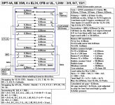
That window is 40x25mm=1000mm^2, it almost equals to EI114, 57x19mm. The biggest disadvantage of EI core is height of window that far too limited, only 19mm. It hard to contain any large coils. It's first time I customed the silicon iron directly from a factory. I amnot satisfaction with that, but it work better than most EI core I have. It can delivery 18W evan at 20Hz, without any observed distortion.This is not about undersizing core afainst neded power, in this example of iron core from the photos, the winding space almpst does not exixsts, it is for special purpose core capable to accept very small nuber of turns... 🙁
How many turns do you need for a coil?
I have many skills and method to increase GM or reduce the Ra of Power tube. By parallelling anohter one, or using CFB wilding and give some local NF to G2, I can highly reducing the Ra of power tube, for example 6L6G, from 2KR triode connection down to 300R. Even at 2.5KR for the RLa I can get a good damping factor, and keeping the primary coils is under 2000turns at same time. So, that windows is enough for me.
I am not looking for a perfect core, just a good one especially that grands of silicon iron is still producing. And make a good wilding for that core with a resonable price.
Last edited:
For SE OT You need higher permeability than ususal is for power transformers.
Load line in LF region is not a flat line but some elipse.
This is not definitive. Especially for low primary Z impedance transformers.
The priority of interest at the elliptical loadlines is entirely up to you. Some designers do not stress it so much. I usually aim for a low-signal unloaded secondary cutoff of -3dB of 5-7Hz in my SE transformers, and a full power capability of 25Hz before saturation knee.
A lowe Z transformer got smaller capacitance than high Z, is that right?2nF is definitely a lot to be driven directly from a tube stage with an output transformer. If we imagine a 1:5 step up transformer, this is 50nF primary reflected capacitance.
A lower reflected primary transformer does not necessarily get smaller capacitance than higher reflected primary impedance.
In fact, the lower you go in primary impedance, the more you can increase capacitance while decreasing leakage inductance.
Lower pimary impedance transformers need more interleaving to keep leakage HF inductance roll-off when transfering power.
On the countrary, you need less interleaving with high primary impedance transformers, where you must decrease capacitance and accept more leakage inductance.
An audio transformer doesn't need to be necessarily interleaved, for example a 30k tube Rp output transformer.
Here's an important tip however. The more you increase leakage inductance, the more careful you need to be with capacitance distribution. Beginners that get slapped by a few dipping resonances rely on paralleled equal turn secondaries, this is your safest bet. Low primary impedance transformers are also easier, they are more forgiving into neglection of capacitance distribution due to their lower leakage inductance primary sections resulted from lots of interleaving. They are also easier on capacitance requirements.
Remember that capacitance decays exponentially from the anode, where at the anode end it is the highest and is equal to the static capacitance, if we assume the secondary is at ground potential, as is the case with most OPTs. At the B+ end you basically get zero capacitance due to the lack of voltage difference between layers there. Remember that to charge capacitance, you need a difference in voltage potential. So the first rule of thumb is keeping the anode far away from ground as possible. Later you can learn tricks like "capacitance dumping", I came on my own with this term. You can learn to deliberately dump capacitance in regions where it's less offensive to the HF response.
In high-z interstage transformers it gets trickier and you need to be more careful with their design. Windings direction and connection are more critical, where if done wrongly, you can have big packages of Cs and Ls resonating into dips, sometimes dangerously close to the audio range.
Last edited:
My Vacuumschmelze databook is full of those permeability curves. I have also data from other manufacturers from all over the world. It’s not so rare as you say. But skip the EI cores.manufacturers rarely give relative permeability data. Most likely that this data You will have to establish with measurements amd calculations. I explained the way how to fing it earlier. From my measurements of diffefent lamination from power xfrm lamination that is aprox value range. (Some C cores have larger about 800...)
...
What value did You find about power transformer lamonations relative permeanility?
Hi 50AEA lower reflected primary transformer does not necessarily get smaller capacitance than higher reflected primary impedance.
In fact, the lower you go in primary impedance, the more you can increase capacitance while decreasing leakage inductance.
Lower pimary impedance transformers need more interleaving to keep leakage HF inductance roll-off when transfering power.
On the countrary, you need less interleaving with high primary impedance transformers, where you must decrease capacitance and accept more leakage inductance.
An audio transformer doesn't need to be necessarily interleaved, for example a 30k tube Rp output transformer.
Here's an important tip however. The more you increase leakage inductance, the more careful you need to be with capacitance distribution. Beginners that get slapped by a few dipping resonances rely on paralleled equal turn secondaries, this is your safest bet. Low primary impedance transformers are also easier, they are more forgiving into neglection of capacitance distribution due to their lower leakage inductance primary sections resulted from lots of interleaving. They are also easier on capacitance requirements.
Remember that capacitance decays exponentially from the anode, where at the anode end it is the highest and is equal to the static capacitance, if we assume the secondary is at ground potential, as is the case with most OPTs. At the B+ end you basically get zero capacitance due to the lack of voltage difference between layers there. Remember that to charge capacitance, you need a difference in voltage potential. So the first rule of thumb is keeping the anode far away from ground as possible. Later you can learn tricks like "capacitance dumping", I came on my own with this term. You can learn to deliberately dump capacitance in regions where it's less offensive to the HF response.
In high-z interstage transformers it gets trickier and you need to be more careful with their design. Windings direction and connection are more critical, where if done wrongly, you can have big packages of Cs and Ls resonating into dips, sometimes dangerously close to the audio range.
Thank you. I appreciated your detialed explanation.
You siad " So the first rule of thumb is keeping the anode far away from ground as possible." Let's using Mr. Turner's drawing as an example. If Point No1 connect to anode, I should avoid make Point A be at ground potential. Am I right?
If a singal swimmng 70Vrms on primary wilding, secondary is only few volt. What the different if I let Point A at ground.
Attachments
Last edited:
- Home
- Amplifiers
- Tubes / Valves
- Winding my own output transformers...dumb idea?