And I doubt your application is dealing with voltages were recycled magnet wire would be a danger anyway. Sort of like doing speaker crossovers.
And in that application you could probably get 50-10kHz without even trying. Try building an EL 34 UL, and things get a little tougher - requiring a lot more inductance. Full audio bandwidth (or beyond) tougher still - and you know how OCD tube-o-philes are.
And in that application you could probably get 50-10kHz without even trying. Try building an EL 34 UL, and things get a little tougher - requiring a lot more inductance. Full audio bandwidth (or beyond) tougher still - and you know how OCD tube-o-philes are.
Starting at 1000Vrms and capacitance as low as possible to avoid to low primary impedance at high frequenciesNever tried sketching one. What kind of voltages are there? What capacitance values?
I read some pages ot the topic. As well as more earlier topics based on same subject, this one miss the most important thing about the audio transformers.
Members mostly talking about impedance and other things not from vital impotrance...
.
1)
The main problem is to find a good core material laminations. From the point of permeability of the alloy.
ths is for designing for optimal number if turns of the primarry. The And it is crucial for good behaviour in the lower end.
Also good and optimal value of permeability, for type of transformer, is strongly connected with air gap value and saturation issues...
.
2)
And preferd geometry is hard to find too. Hiher, wider window to place all the windings and isolation is welcome. (Not the standard for power transformers because of need for improved isolation, and advanced winding oprions.) That is to beat leakage inductances and capacitances to have wider HF range AND with minimum phase shift. And to decrease Mutual condctance of the transformer.
That is also a need because wider diameter of wire that will decrease Rdc of the primary windings.
...
Ususaly people take a unapropriate laminations for power tranformers they are of low permeability. It is not posibile to acheive good Primary inductance in Henry-s. That leads to cuttig out the Bass region with huge phase shift. And that is the reason why most of the SE power amps are "weak" in the bass. That value is strongly connected with Ri internal resistance of Tube... That will lead to wrong inrease of the nuber of turns in primary to have more Hy, but that way "eating" the space of window, decresaind space for islolation, increasing the number of secondary turns.
/
Increasing the Core area will lead to incresing he lenght of wire in the primary and Rdc, inresing the area for capacitance damaging the LF region, HF region. And the "balanse" of copper / iron. Diturbing ratio of losses in copper and iron. Idealy core has to be from square area.
/
Divide fixed core lenght with thickness of the lamination to determine number of laminations for square ratio.
That ususaly will lead to use non standard winding body...
/
So first step should be to chose Core of say 800 permebility. For transformers with DC magnetization. The power transformers have cores of 250 - 400 permeability. This could be done by setting the test coil of different number of turns 100-200-500 and measure coil inductance for each number of turns. BUT with each nuber of turns change say 3 diferent values of GAP. That 9 tesults put in the formula and calculate value of Permeability. All of the results will gravitate to one value. If the value is 200-400 that core material is NOT suitable for Output transformer.
/
It is very hard to find cores with bigger space for windings. That space is not havs to be full filled with copper. we need a primmary as close to the core...
/
And thickness of lamination shuld be 0.25mm to max 0.35mm.

HiI read some pages ot the topic. As well as more earlier topics based on same subject, this one miss the most important thing about the audio transformers.
Members mostly talking about impedance and other things not from vital impotrance...
.
1)
The main problem is to find a good core material laminations. From the point of permeability of the alloy.
ths is for designing for optimal number if turns of the primarry. The And it is crucial for good behaviour in the lower end.
Also good and optimal value of permeability, for type of transformer, is strongly connected with air gap value and saturation issues...
.
2)
And preferd geometry is hard to find too. Hiher, wider window to place all the windings and isolation is welcome. (Not the standard for power transformers because of need for improved isolation, and advanced winding oprions.) That is to beat leakage inductances and capacitances to have wider HF range AND with minimum phase shift. And to decrease Mutual condctance of the transformer.
That is also a need because wider diameter of wire that will decrease Rdc of the primary windings.
...
Ususaly people take a unapropriate laminations for power tranformers they are of low permeability. It is not posibile to acheive good Primary inductance in Henry-s. That leads to cuttig out the Bass region with huge phase shift. And that is the reason why most of the SE power amps are "weak" in the bass. That value is strongly connected with Ri internal resistance of Tube... That will lead to wrong inrease of the nuber of turns in primary to have more Hy, but that way "eating" the space of window, decresaind space for islolation, increasing the number of secondary turns.
/
Increasing the Core area will lead to incresing he lenght of wire in the primary and Rdc, inresing the area for capacitance damaging the LF region, HF region. And the "balanse" of copper / iron. Diturbing ratio of losses in copper and iron. Idealy core has to be from square area.
/
Divide fixed core lenght with thickness of the lamination to determine number of laminations for square ratio.
That ususaly will lead to use non standard winding body...
/
So first step should be to chose Core of say 800 permebility. For transformers with DC magnetization. The power transformers have cores of 250 - 400 permeability. This could be done by setting the test coil of different number of turns 100-200-500 and measure coil inductance for each number of turns. BUT with each nuber of turns change say 3 diferent values of GAP. That 9 tesults put in the formula and calculate value of Permeability. All of the results will gravitate to one value. If the value is 200-400 that core material is NOT suitable for Output transformer.
/
It is very hard to find cores with bigger space for windings. That space is not havs to be full filled with copper. we need a primmary as close to the core...
/
And thickness of lamination shuld be 0.25mm to max 0.35mm.
For more space for cooper and isolantion, use double C core with europeen sizes, They get too much space §
Yan
Excuse me but No... 🙁Hi
For more space for cooper and isolantion, use double C core with europeen sizes, They get too much space §
Yan
It is not for the best results. Dual C cores nas a little or no extra space with standard cores dimensions.
...
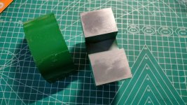
BUT oter problem is present with C cores:
They are made from widing strip lamination in "O" shape. And that is OK if the core stays in that physical form.
But it not that happens latter...
Then the compact "O" shape is cutting into halfs to get the 2 x "C" shape.
In That cutting temperature risinig in the cuting area of lamination stack at 2 sides each cut.
That changing eletro magnetic chrs in that area.
Even if that cut made by cold water jet the laminations after polishind wil merge into one pretty solid area...
That is clarly visibile...
AND another thing that is maybe more questionable is that after cutting into 2 "C" shapes, C are foing to polishing tha area of contact.
In that proceses ends of laminations are melting together. So we dont have separate thicknes laminations anu more but all of the laminations are merging into one area... Plus another thermal disturbance...
We have 2+2+2+2=8 area with merged lamination into single areas, in the direct path of air gap formed.
...
The main advantage and purpose of "C" cores that they are super easy to pack and unpack if needed. And thae Are for other transformers or chokes - not the close to the best for the OT or interstage.
Last edited:
Hi Zoran1)
The main problem is to find a good core material laminations. From the point of permeability of the alloy.
ths is for designing for optimal number if turns of the primarry. The And it is crucial for good behaviour in the lower end.
Also good and optimal value of permeability, for type of transformer, is strongly connected with air gap value and saturation issues...
I could't agree with you. I ran lots of tests with many of Silicon iron I can get. It came from UK, Gemary, US, J apan, and also China they made in recent decades. Considering the different AFE, and ML for each iron, I wound turns of 80~300 for individual one. The results are very interesting, almost each different item shows different behave.
I applyed 10vrms sine wave at 10~1000Hz for the coil. Some of them show alot of distortion at lower frequency. One of them have a same distortion from 40Hz up to 120Hz, looks like have a constant pereability. A few of them have very low distorion evan at 10~20Hz.
Finally, I choise a type of silicon iron which performance is best, and it is still manufacturing. The thickness is 0.23mm, high permeablilty grade. I also noticed that Silicon iron is a shape sensitive material. C type or CD type is better than EI.
I palced a order to a local factory and received it. 😎
Andy
Attachments
Hi Finesea
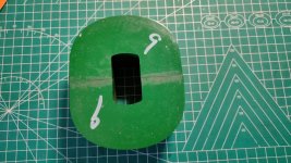
That is exact problem that I am talking about
The core area are strongly ovesized against the winding area
+
The laminations are merged around the area of conntact.
That is exact problem that I am talking about
The core area are strongly ovesized against the winding area
+
The laminations are merged around the area of conntact.
The temperature in cutting area will rising but not high above 700 degrees Celsius. The iaminations are merged that is a problem. But I don't find a better solution than C Core.
For interstage transformers the things are pretty much the same BUT with one main diference optionaly we dont have DC magnetisation.
.
One of the crucail thing is Primary inductance and Rdc
This is the start for any consideration.
.
Why members dont mention this key values any more?
within the source output resistance these 2 values have total control of tje phase and transfer in LF.
.
One of the crucail thing is Primary inductance and Rdc
This is the start for any consideration.
.
Why members dont mention this key values any more?
within the source output resistance these 2 values have total control of tje phase and transfer in LF.
This is a non argument because all transformer have the same problem, inner diameter is different from outer diameter, even if it’s EI core. But there are options for less big differences. The “ideal” core ratio is 1:1,25Hi Finesea
That is exact problem that I am talking about
The core area are strongly ovesized against the winding area
+
The laminations are merged around the area of conntact.
For interstage try to find EI or M laminations. If there is no magnetization DC, small signal only, the permaeability should be higher. Permalloy type.
If there are some DC the gap should be increased. Sometimes it is not the solution, and that will dramaticaly decrese Primary inductance.
.
The Source impednace is first thing should be determinated. Measure and calculate. That is not the classic wrong impedance like 600ohms or 200ohms or so
If there are some DC the gap should be increased. Sometimes it is not the solution, and that will dramaticaly decrese Primary inductance.
.
The Source impednace is first thing should be determinated. Measure and calculate. That is not the classic wrong impedance like 600ohms or 200ohms or so
Sorry but not.This is a non argument because all transformer have the same problem, inner diameter is different from outer diameter, even if it’s EI core. But there are options for less big differences. The “ideal” core ratio is 1:1,25
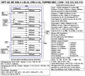
Look at the standard height of windings window this is 1/2 of width of "E" of the core. But there are also standard lamination with almost double height of the window that is same height as middle "E" laminates. Or "M"
.
Lenght of magnetic lines are only longer (with bigger window/same core area) and that its also a factor.
Maybe but measuring all laminations with insulation? That will increase one side of square...The “ideal” core ratio is 1:1,25
The normal way is to simply divide the width of middle "E" length with d of lamination.
For the example 4cm "E" and d=0.35
giving around 114 to 115 laminations for square iron core.
But counting lamination insulation, that will be more than 4 cm at the end because we have 2x114 times of laminaton insulation.
If we shrink core area, the power can be delivered by core is also decreased. We can increase the winding room, but that will add more magnetic length, and more turns of primary.Hi Finesea
That is exact problem that I am talking about
The core area are strongly ovesized against the winding area
+
The laminations are merged around the area of conntact.
By the way, the window area for winding is enough for me.
I meant self-capacitance of the speakers themselves.Starting at 1000Vrms and capacitance as low as possible to avoid to low primary impedance at high frequencies
I read some pages ot the topic. As well as more earlier topics based on same subject, this one miss the most important thing about the audio transformers.
When designing a transformer, it's important to focus on getting a balance of as many parameters as possible. And the recipe for this balance is up to you. Good or bad transformer, everyone has different preferences here. Deducted from this logic, I find defining a transformer as good or bad as obsolete.
In my cookbook, I start with the basic requested parameters. Primary impedance, impedance ratio, maximum power output per frequency, maximum permissible Rdc losses, inductance and Idc (SE). Then I select a core, interleaving, number of turns and check the leakage inductance. If the later is satisfactory, I sketch the interleaving, calculate and distribute capacitances. Capacitance distribution is important and is unique for specific projects (high, low Z OPT, step-ups, phase splitters).
Well, as a kid this was the only way for me to get my hands on enamelled wire. I just unwound transformers from old radios, TV sets etc., wound the wire on spools for storage and used them to wind new transformers exactly according to my own specs. Of course I rather quickly learned not to reuse enamelled wires from impregnated transformers, just to avoid getting my fingers cut by the sharp edges 😉 . Some of my old homebrewn transformers still work these days.Salvaged wire????? 😱
Avoid it like the pest it is.
Best regards!
All transformer laminations have a isolation on both side otherwise there is to much eddycurrent. EI i never want because of bad physical properties. EI is for cheap solutions.Maybe but measuring all laminations with insulation? That will increase one side of square...
The normal way is to simply divide the width of middle "E" length with d of lamination.
For the example 4cm "E" and d=0.35
giving around 114 to 115 laminations for square iron core.
But counting lamination insulation, that will be more than 4 cm at the end because we have 2x114 times of laminaton insulation.
Hi 50AEI meant self-capacitance of the speakers themselves.
When designing a transformer, it's important to focus on getting a balance of as many parameters as possible. And the recipe for this balance is up to you. Good or bad transformer, everyone has different preferences here. Deducted from this logic, I find defining a transformer as good or bad as obsolete.
In my cookbook, I start with the basic requested parameters. Primary impedance, impedance ratio, maximum power output per frequency, maximum permissible Rdc losses, inductance and Idc (SE). Then I select a core, interleaving, number of turns and check the leakage inductance. If the later is satisfactory, I sketch the interleaving, calculate and distribute capacitances. Capacitance distribution is important and is unique for specific projects (high, low Z OPT, step-ups, phase splitters).
I read all Partick Turner 's article about OPT, I found there is a few way for interleaving. Did I miss something? Can you give me some tips?
Andy
Attachments
The self capacitance depends on the design, segmented or not segmented esl. Not segmented can be easely up to 2nF, segmented too but for the full-range part it is between 80-150pF and for the other sections a lot more but they are missing more or less the high, mid-high frequenciesI meant self-capacitance of the speakers themselves.
When designing a transformer, it's important to focus on getting a balance of as many parameters as possible. And the recipe for this balance is up to you. Good or bad transformer, everyone has different preferences here. Deducted from this logic, I find defining a transformer as good or bad as obsolete.
In my cookbook, I start with the basic requested parameters. Primary impedance, impedance ratio, maximum power output per frequency, maximum permissible Rdc losses, inductance and Idc (SE). Then I select a core, interleaving, number of turns and check the leakage inductance. If the later is satisfactory, I sketch the interleaving, calculate and distribute capacitances. Capacitance distribution is important and is unique for specific projects (high, low Z OPT, step-ups, phase splitters).
2nF is definitely a lot to be driven directly from a tube stage with an output transformer. If we imagine a 1:5 step up transformer, this is 50nF primary reflected capacitance.
Patrick has quoted some types of OPT interleaving, just keep exploring his website. He has given explanations behind his reasons, although they can be scatered around. He has also explained how to calculate primary to secondary capacitance.
Hi 50AE
I read all Partick Turner 's article about OPT, I found there is a few way for interleaving. Did I miss something? Can you give me some tips?
Andy
Patrick has quoted some types of OPT interleaving, just keep exploring his website. He has given explanations behind his reasons, although they can be scatered around. He has also explained how to calculate primary to secondary capacitance.
- Home
- Amplifiers
- Tubes / Valves
- Winding my own output transformers...dumb idea?