
I'm working on it now, but it will take some time.
How about an L-pad next to the driver to start. This will bring it down 6dB and smooth the impedance. It will also mean you don't need the same resistor and capacitor as the woofer circuit. (By the way, you can find L-pad calculators online just for now)
Next you can use the capacitor and inductor from the tweeter circuit, or just the capacitor.
Then add the woofer inductor. Total of 4 or 5 components. (I'll have to review this after making the demonstration graphics.)
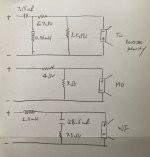
Not sure if I understood correctly and based on what I understood, I drew the crossover for 3 ways as attached. I added L-Pad for both Tweeter and Midrange and added Zobel circuit on Woofer. Not sure if I need to add an inductor and caps on midrange though. Hope I am not totally misunderstood.
Attachments
My bad, it's the way I said it.
The L-pad looks OK. Now you can alternately pretend the mid is the tweeter being crossed to the woofer as a two way, then pretend it is the woofer being crossed to the tweeter. This way those extra components get added to the mid to the left of the 4 ohm resistor... except with different values that suit the mid itself.
Tell me if I'm making sense yet. Here's what I wrote earlier about this...
but instead of 'tweeter circuit' I meant to say from the 'tweeter circuit post' using the midrange in its place.Next you can use the capacitor and inductor from the tweeter circuit, or just the capacitor.
Then add the woofer inductor.
My bad, it's the way I said it.
The L-pad looks OK. Now you can alternately pretend the mid is the tweeter being crossed to the woofer as a two way, then pretend it is the woofer being crossed to the tweeter. This way those extra components get added to the mid to the left of the 4 ohm resistor... except with different values that suit the mid itself.
Tell me if I'm making sense yet. Here's what I wrote earlier about this...
but instead of 'tweeter circuit' I meant to say from the 'tweeter circuit post' using the midrange in its place.
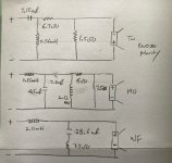
Thank you, Allen. To be honest, I am not 100% sure if I followed you correctly and treat the mid-driver as tweeter as well as woofer. Then, came up with this modified crossover schematic.
In short, 2 additional inductors and 2 additional capacitors were added in the Midrange and also replaced L-Pad resistor values to 6 ohm & 7.5 ohm respectively.
Attachments
That's the way, and that circuit should work.
One of the things to be aware of is that if you bring the two crossover points close together then they can interact.. not that it has to be a problem. If you're ever looking for an excuse to do some simulating.
The question of first or second order (for both the low and high pass sections, and whether you should keep one or two of those components) is more a matter for experimentation here. There was some mention of it in the tutorial but the factors involved (the driver depths, responses and frequencies involved) may be different with a 3 way.
Hi, would someone be interested to suggest a cross over for the following MTM:
https://www.parts-express.com/TC-8034-8-Treated-Paper-Cone-Woofer-with-Foam-Surround-4-Oh-299-2200
https://www.newark.com/mcm-audio-select/53-805/3-x-7-piezo-horn-tweeter/dp/96K1143?st=tweeter
I'm building a set of high efficiency speakers for outdoor parties. I like the MTM arrangement to get better power handling and loudness.
There are no measurements for these drivers I'm aware of. So I'd like to keep the crossovers as simple as possible. From initial listening crossoverless (I've built the boxes already), The tweeters wont need any attenuation. And I have a good feeling about crossing 2.5k and higher. They will be used with subs. I've had good success in the past with the online calculators, at least for party speakers, but I don't know how to design for piezos. The woofers are 4ohms so would I series the woofers and then parallel with the tweeter etc?
You can treat the two woofers as one 8 ohm unit and follow the tutorial as normal... However, MTM is a good opportunity for a 2.5 way. In a 2.5 way both woofers play bass, and one rolls off at the baffle step frequency (say 600Hz) and the other plays up to the crossover. This usually gives a fairly easy baffle step compensation, which helps if you do this without measurement. Another is that it avoids the narrowing vertical dispersion that MTM unfortunately has below the crossover if you can't cross them really low.
Since you have them in series, you'll need a couple of extra components. C1 causes the woofer labelled S2 to roll off at 600Hz. R1 and L2 make sure woofer S1 stays steady while that happens. L1 is the actual crossover at 2,500Hz. If you have any problems at the crossover you can add the RC zobel circuit across S1 as described in the section about flattening the impedance of the woofer.

Crossing piezos is different because they are a capacitive load for the amplifier. Here is a small writeup on the basics - http://www.frugal-phile.com/piezo-XO.html
Since you have them in series, you'll need a couple of extra components. C1 causes the woofer labelled S2 to roll off at 600Hz. R1 and L2 make sure woofer S1 stays steady while that happens. L1 is the actual crossover at 2,500Hz. If you have any problems at the crossover you can add the RC zobel circuit across S1 as described in the section about flattening the impedance of the woofer.
Crossing piezos is different because they are a capacitive load for the amplifier. Here is a small writeup on the basics - http://www.frugal-phile.com/piezo-XO.html
Ok! So from the piezo article. It says I should use a 22ohm resistor parallel to the tweeter, and then a 2.2uF cap inline, this would effectively be a 3khz highpass. At what slope I have no idea. probably doesn't matter.You can treat the two woofers as one 8 ohm unit and follow the tutorial as normal... However, MTM is a good opportunity for a 2.5 way. In a 2.5 way both woofers play bass, and one rolls off at the baffle step frequency (say 600Hz) and the other plays up to the crossover. This usually gives a fairly easy baffle step compensation, which helps if you do this without measurement. Another is that it avoids the narrowing vertical dispersion that MTM unfortunately has below the crossover if you can't cross them really low.
Since you have them in series, you'll need a couple of extra components. C1 causes the woofer labelled S2 to roll off at 600Hz. R1 and L2 make sure woofer S1 stays steady while that happens. L1 is the actual crossover at 2,500Hz. If you have any problems at the crossover you can add the RC zobel circuit across S1 as described in the section about flattening the impedance of the woofer.
View attachment 1095128
Crossing piezos is different because they are a capacitive load for the amplifier. Here is a small writeup on the basics - http://www.frugal-phile.com/piezo-XO.html
And then if I follow your crossover for the woofers, I'm low passing one woofer at 600Hz, and the other at 2.5kHz.
And then I should wire the woofers and tweeter in parallel? Then what impedance range will the amp see? Will this be more of a 4ohm or 8ohm speaker or somewhere in between?
What kind of problems might I experience if I don't flatten the impedance of the woofer?
Is impedance flattening and/or baffle step compensation always worth it?
The piezo would be first order. They can handle being crossed like this and the only reason to change it is if you think it sounds wrong.At what slope
Yes.. Wait, I used generic 8 ohm drivers in that sim by mistake. No problem... for the starter values for 4 ohms, halve the inductor and resistor values and double the capacitor.I'm low passing one woofer at 600Hz, and the other at 2.5kHz.
Closer to 8 ohms.Will this be more of a 4ohm or 8ohm speaker
The woofer might have more high frequency energy than you want. If this happens you could even try a larger inductor before instead trying the zobel.What kind of problems might I experience if I don't flatten the impedance of the woofer?
You'll probably miss the baffle step compensation, especially if you go taking them outside.Is impedance flattening and/or baffle step compensation always worth it?
The piezo would be first order. They can handle being crossed like this and the only reason to change it is if you think it sounds wrong.
Would it then be a bad idea to also use first order crossovers for the woofers?
You seem to be referring to the side benefit of using second order causing a little extra delay because the tweeter is closer to the surface of the baffle. Without measurement it's still only a guess but if you are not sitting at exactly tweeter level, switching the upper and lower woofers places could give you the variation you need.
If my boxes are 12" wide, should I roll off S2 at 380Hz or so instead of 600? If so how should the values change for these 4ohm drivers?In a 2.5 way both woofers play bass, and one rolls off at the baffle step frequency (say 600Hz) and the other plays up to the crossover.
Also how/why would the woofers being in series increase the number of components? How would it look like in parallel? Not that I want my speaker to be 2ohms, I just want to understand the circuit more. (though I do have both car amps and PA amps that can drive 2 ohm loads for extra power.)
First with this post I'll describe the series circuit.
1. I've put 8 ohm resistors in parallel with the drivers for the simulation to make them act like 4 ohm drivers. Do not add them to your crossover.
2. I made this change...
3. Then I adjusted the capacitor and the middle inductor together to make the baffle step frequency change.
Tweaking: While everything is open to tweaking, notice that the top end is down 3dB at 2.5kHz. Some crossovers are down at 6dB at the cross. These are not the frequencies you want too much energy. It might turn out necessary to try larger values for the top inductor, even twice as much.

Everything is scalable. There are 3 things to note...how should the values change for these 4ohm drivers?
1. I've put 8 ohm resistors in parallel with the drivers for the simulation to make them act like 4 ohm drivers. Do not add them to your crossover.
2. I made this change...
for 4 ohms, halve the inductor and resistor values and double the capacitor.
3. Then I adjusted the capacitor and the middle inductor together to make the baffle step frequency change.
Tweaking: While everything is open to tweaking, notice that the top end is down 3dB at 2.5kHz. Some crossovers are down at 6dB at the cross. These are not the frequencies you want too much energy. It might turn out necessary to try larger values for the top inductor, even twice as much.
Last edited:
An easy circuit when in parallel. I normally don't go for the series option when I have a choice when doing a 2.5 way.. in this case it's just that the MTM is also a tricky option and it's hard to say which is better.How would it look like in parallel?
The simplest parallel 2.5 way...
In addition, the Zobel (RC) circuit may be added to the woofer that plays up to the crossover frequency.
They share the amplifier drive Voltage. As I remove the higher frequency energy from the baffle step woofer, the other one tries to compensate. (Recreating a finite, non-infinite, non-zero impedance from within the middle of a circuit requires both series and parallel components.)Also how/why would the woofers being in series increase the number of components?
It seems in my situation going from MTM 2 way to 2.5way to deal with BSC might not be worth it, In series, the capacitor gets really big. EQing seem more practical here....
Ok, you can treat the two as a single 8 ohm driver when working out the inductor. Work out the resistor and capacitor as for one woofer, then double the resistance and halve the capacitance.
The other thing to note when using two in series is that the total sensitivity stays the same as for one woofer.
Edit: Added.
The other thing to note when using two in series is that the total sensitivity stays the same as for one woofer.
Edit: Added.
Last edited:
The piezo article call for 2.2uf and 22ohm for the high pass. I already have 0.4mh coils for the 3khz 1st order low pass. I really don't know any of the differences between all the different kinds of capacitors and resistors!
Is this a suitable capacitor?
https://www.newark.com/panasonic/ecw-fe2w225pl/cap-2-2uf-450v-film-radial/dp/33AH7229
And resistor
https://www.newark.com/multicomp-pro/mcmf0w8ff220ja20/metal-film-resistor-22-ohm-125mw/dp/58K3911
Is this a suitable capacitor?
https://www.newark.com/panasonic/ecw-fe2w225pl/cap-2-2uf-450v-film-radial/dp/33AH7229
And resistor
https://www.newark.com/multicomp-pro/mcmf0w8ff220ja20/metal-film-resistor-22-ohm-125mw/dp/58K3911
The capacitor is fine, it's polypropylene film with a Voltage rating above 50V.
I wouldn't recommend the resistor unless you are certain otherwise, as it is low powered and metal film. The standard resistor for speakers is wirewound and 5W. The power requirements do vary greatly but these cover most situations. As previously discussed, resistors should be checked in use to make sure the power rating is satisfactory.
I wouldn't recommend the resistor unless you are certain otherwise, as it is low powered and metal film. The standard resistor for speakers is wirewound and 5W. The power requirements do vary greatly but these cover most situations. As previously discussed, resistors should be checked in use to make sure the power rating is satisfactory.
Got it. I had no idea about the resistor. while the cap looks not like the usual "audio grade" ones. Here is a 10W wirewound I'll order,
https://www.amazon.com/Resistors-Wi...=wirewound+resistor+22ohm,aps,110&sr=8-4&th=1
https://www.amazon.com/Resistors-Wi...=wirewound+resistor+22ohm,aps,110&sr=8-4&th=1
The Sound of CapacitorsI really don't know any of the differences between all the different kinds of capacitors, resistors
Resistor design
Last edited:
- Home
- Loudspeakers
- Multi-Way
- Introduction to designing crossovers without measurement