What about the people I speak to? Oh, you might have forgotten that I don't just have readers. We speak down here and the language we speak is called English. You should try it sometime. lolJoe,
When you try to make it simple is when you confuse your readers.
I do assume you are in an English-speaking country, just a bit of Oz humour.
BTW, you address my name Joe and then you criticise me. Fair enough, but may I ask what your name is? That way we can be on a first-name basis. Seems fair to me.
You have now posted seventy-four times in a matter of weeks, that's a lot of times. In the meantime, you have posted nowhere else. Interesting...?
You also have one incredibly annoying habit and in your last post, you did it again, like a serial offender:
You keep sending me links that I have already read!
Did it not occur that I might even have read them before you?
It is annoying, it is presumptuous and not a little bit condescending. But it does make me wonder.
But most of all, stop being a ghost, and please, at least tell me your first name.

good question. It has apparently been around for a long time and Klippel has used it for ages. The other models are Leach and Wright but they use fractional order model that cannot be represented by a real circuit (eg calculating the time domain response is extremely complicated). Later, Thorborg from Peerless introduced some another fractional order models based on a semiconductor (Z= sqrt(s)).@lrisbo ,
You are the person that could know.
What is the origin of the L2R2 voice coil theory?
I lave looked and relooked but I have not found any AES papers.
What is the L2R2 theory history.
Thanks DT
I have used two LR sections is series plus an inductor which can fit most drivers really well and can be applied is circuit and xover simulators.
Hello Joe and All,
After the markets closed I spent some time reading this paper.
Comparative Measurements on Loudspeaker Distortion: Current vs. Voltage Control
Esa MERILAINEN
Yes I have read it before, this time I focused on V / I conversion. The term V / I conversion shows up 12 times in this paper. The theme is that EMF causes serious current distortion as the driver converts input voltage to current.
All the distortion measurements were taken at Small signal levels. You know at about 1 Watt or less. 2.83V RMS as well as 2.00 Volts was also mentioned in the paper.
My measurements of the P17WJ 00 08 are consistent with the results in the paper.
It is my impression that driver Voltage to Current conversion needs to be included in the driver distortion “KISS” model.
If you are inviting me to lunch you can call me Bob.
Thanks DT
Hi Delta
Yes, quite familiar with this paper too, he has done it with very modest equipment. I will be doing something both similar, but I have in mind looking at certain things a little deeper. I need more headroom and push things harder than he has. I think the Sennheiser E815 has limitations when it comes to nearfiled. I want to press the driver harder, much harder, but not too hard. I have a genuine measurement mike that has 140dB and headroom to do nearfield stuff and also much lower distortion (it's also mightily more expensive). I have a theory in mind I need to explore. Using another measurement technique by somebody I know in the Netherlands and I want to confirm it in a different way, . it will validate why current EQ and flat current phase angle can reduce distortion in certain types of amplifiers while other types of amplifiers, like tubes and Class D, largely avoids it. Let us see...
Yes, the P17WJ8 is very suitable for this kind of testing. That is why I mentioned it earlier.

Current distortion.
But what is distorting? The driver or the amplifier?
If the current is distorted, then where does the current come from? The speaker does not produce current, the amplifier does.
Yes, the driver has its own distortion. It's still there with current drive. The driver will never be distortion free. So what he calls 'voltage control' results in more distortion. I am not yet sure that he understands that this is the amplifier that is making the situation worse. The nature of a voltage source is that it has zero control control over the current. I like it to the amplifier getting bossed around by the driver and the amplifier adds to the existing distortion already in the driver. The current distortion we measure with a current sense resistor is measuring the current of the amplifier and finding current distortion. Then we look on the acoustic side and sure enough, it's there!
As far as the KISS thing, I am not sure if I am going to be able to successfully get it across here.
So I will only briefly give it another go:
If we measure a driver with nominally 1W input (2.83V) and we measure the output with our microphone and get 90dB-SPL/1M.
To get that output result (or whatever the value that shows up in dB), then you have taken anything and everything into account to get to that value, 90dB.
Now we could have endless discussions about endless things about how we got to 90dB. They are all important in their own right. But we got to 90dB, now what?
It is not how we got 90dB-SPL that interests me, it is how we get from 90dB-SPL to 96dB-SPL.
We simply used 2.83V to get a certain amount of current going through the voice coil.
To get to 96dB we now have to make sure 2x the current passes through the VC. That will get us 96dB. If we want to go backward and get 84dB, then we need 0.5x the current. Up and down. What is music that we are listening to? It is simply that current going up and down at different rates (simulating dynamics and different frequencies) and that is what we hear.
Music can be characterised by the rate of change of current and that is what you are listening to.
Just getting to 90dB is not music, changing 90dB level is!
Once we have reached this stage the proportion of current must be just right, proportionanilty becomes the only goal. How well we achieve that is paramount.
With whatever level of precision and accuracy it does this, any deviation is distortion.
Looking at it this way is what I mean by KISS.
I also note once again that Esa refers to the prevalence odd-order distortion. I believe it is the amplifier that is producing this distortion, although the driver is an accomplice. If we have current distortion, where does the current come from? The amplifier.
Cheers, Joe
Yes, quite familiar with this paper too, he has done it with very modest equipment. I will be doing something both similar, but I have in mind looking at certain things a little deeper. I need more headroom and push things harder than he has. I think the Sennheiser E815 has limitations when it comes to nearfiled. I want to press the driver harder, much harder, but not too hard. I have a genuine measurement mike that has 140dB and headroom to do nearfield stuff and also much lower distortion (it's also mightily more expensive). I have a theory in mind I need to explore. Using another measurement technique by somebody I know in the Netherlands and I want to confirm it in a different way, . it will validate why current EQ and flat current phase angle can reduce distortion in certain types of amplifiers while other types of amplifiers, like tubes and Class D, largely avoids it. Let us see...
Yes, the P17WJ8 is very suitable for this kind of testing. That is why I mentioned it earlier.
Current distortion.
But what is distorting? The driver or the amplifier?
If the current is distorted, then where does the current come from? The speaker does not produce current, the amplifier does.
Yes, the driver has its own distortion. It's still there with current drive. The driver will never be distortion free. So what he calls 'voltage control' results in more distortion. I am not yet sure that he understands that this is the amplifier that is making the situation worse. The nature of a voltage source is that it has zero control control over the current. I like it to the amplifier getting bossed around by the driver and the amplifier adds to the existing distortion already in the driver. The current distortion we measure with a current sense resistor is measuring the current of the amplifier and finding current distortion. Then we look on the acoustic side and sure enough, it's there!
As far as the KISS thing, I am not sure if I am going to be able to successfully get it across here.
So I will only briefly give it another go:
If we measure a driver with nominally 1W input (2.83V) and we measure the output with our microphone and get 90dB-SPL/1M.
To get that output result (or whatever the value that shows up in dB), then you have taken anything and everything into account to get to that value, 90dB.
Now we could have endless discussions about endless things about how we got to 90dB. They are all important in their own right. But we got to 90dB, now what?
It is not how we got 90dB-SPL that interests me, it is how we get from 90dB-SPL to 96dB-SPL.
We simply used 2.83V to get a certain amount of current going through the voice coil.
To get to 96dB we now have to make sure 2x the current passes through the VC. That will get us 96dB. If we want to go backward and get 84dB, then we need 0.5x the current. Up and down. What is music that we are listening to? It is simply that current going up and down at different rates (simulating dynamics and different frequencies) and that is what we hear.
Music can be characterised by the rate of change of current and that is what you are listening to.
Just getting to 90dB is not music, changing 90dB level is!
Once we have reached this stage the proportion of current must be just right, proportionanilty becomes the only goal. How well we achieve that is paramount.
With whatever level of precision and accuracy it does this, any deviation is distortion.
Looking at it this way is what I mean by KISS.
I also note once again that Esa refers to the prevalence odd-order distortion. I believe it is the amplifier that is producing this distortion, although the driver is an accomplice. If we have current distortion, where does the current come from? The amplifier.
Cheers, Joe
Still, if one can't measure it outside the system/speaker - whats the point?
"Dramatic" should show easy - no?
//
"Dramatic" should show easy - no?
//
That got me thinking and started measuring the driver below.
SB17NRXC35-8 (discontinued):
1KHz 0.15mH, 2KHz 0.104mH, 4KHz 85uH, 8KHz 71uH, 10KHz 68uH, 15KHz 64uH, 20KHz 63uH, 50KHz 61uH
Now that's a pretty low inductance driver, used in the first Elsinore Mk6 "NRX" that nany on this forum are listening too. The "MFC" driver is almost the same.
Note that gradually above 10KHz the inductance flattens out. I also checked 100KHz and that was 58uH.
Add a 0.22mH external (much more stable) inductor directly in series with the VC and you are reducing back-EMF effects at 1KHz and above by quite a few percent and by 10KHz the ratio is better than 3:1 . Even when the inductance is varying with excursion, which we know this driver does because in this department it is not flat like the Purifi drivers, you get a benefit in flattening the impedance/current modulations (of the amplifier).
I have been doing this for at least ten years now and heard the difference from the very beginning. Some say 'prove it' and I say 'try it.'
Below is how it is applied in a 2-Way with the added bonus of current EQ which locks in both the bass alignment and the crossover and presents a flat current phase angle to the amplifier:

Of course, driver selection is important.
Adjust L1 to be -6dB @ 3KHz, and adjust C1 also to be -6dB @ 3KHz (waveguide is useful here). The L2/C2 is a null filter tuned to the Fb of the tweeter, the Q is adjusted to give you that flattest FR at and below the 3KHz crossover.
The above is not that hard to do if you set your mind to it. Adjust values so that the best FR is about 15 degrees off axis, never straight on axis. Just my experience.
Cheers, Joe
SB17NRXC35-8 (discontinued):
1KHz 0.15mH, 2KHz 0.104mH, 4KHz 85uH, 8KHz 71uH, 10KHz 68uH, 15KHz 64uH, 20KHz 63uH, 50KHz 61uH
Now that's a pretty low inductance driver, used in the first Elsinore Mk6 "NRX" that nany on this forum are listening too. The "MFC" driver is almost the same.
Note that gradually above 10KHz the inductance flattens out. I also checked 100KHz and that was 58uH.
Add a 0.22mH external (much more stable) inductor directly in series with the VC and you are reducing back-EMF effects at 1KHz and above by quite a few percent and by 10KHz the ratio is better than 3:1 . Even when the inductance is varying with excursion, which we know this driver does because in this department it is not flat like the Purifi drivers, you get a benefit in flattening the impedance/current modulations (of the amplifier).
I have been doing this for at least ten years now and heard the difference from the very beginning. Some say 'prove it' and I say 'try it.'
Below is how it is applied in a 2-Way with the added bonus of current EQ which locks in both the bass alignment and the crossover and presents a flat current phase angle to the amplifier:
Of course, driver selection is important.
Adjust L1 to be -6dB @ 3KHz, and adjust C1 also to be -6dB @ 3KHz (waveguide is useful here). The L2/C2 is a null filter tuned to the Fb of the tweeter, the Q is adjusted to give you that flattest FR at and below the 3KHz crossover.
The above is not that hard to do if you set your mind to it. Adjust values so that the best FR is about 15 degrees off axis, never straight on axis. Just my experience.
Cheers, Joe
Current distortion.
But what is distorting? The driver or the amplifier?
If the current is distorted, then where does the current come from? The speaker does not produce current, the amplifier does.
Voltage comes from the amplifier. The driver converts Voltage to Current, by V / I Conversion.
The current is distorted by driver Back EMF. This concept is supported by L2 R2, Leach and Wright driver impedance models.
Assumptions need to be tested.
Thanks DT
yes, it’s measurable. most drivers have in their mid band odd harmonics totally dominated by motor hysteresis distortion when voltage driven. in current drive, this goes away and we see the residual distortion from eg the moving partsSo it should really be readily measurable in the acoustic domain if done right?
Like: Meas1=Voltage drive, Meas2=current drive - everything else equal - look at the difference distortion wise!!.. kind of comparison.
But with a FR penalty at resonances...
//
The current is distorted by driver Back EMF.
Agreed. But the current of what?
Agreed. But the current of what?
Hello Joe,
Asked and answered.
The amplifier makes Volts, the driver converts Volts to current. Back EMF distorts the current.
That is the Keep It Simple System.
Time to post some test results.
Post 5019 shows a, L2 R2 calculated, Zobel that flattens both Impedance and Phase Angle curves will not necessarily reduce distortion. The amplifier looks to perform the same with or without the Zobel.
A parallel Zobel did not reduce distortion.
A series 7R resistor did reduce distortion a couple or 3 dB on the SINAD.
Thanks DT
I understand that the goal is to take a box of passive parts, inductors, capacitors and resistors and use them to improve the performance of a plain jane drive in an effort to approach the performance of a current drive amplifier. "As good as."
I am with you.
I'm not sure if this has already been posted but this paper from Hawksford and Mills was linked by Bruno Putzey's in an old Pro Sound Web forum post about Esa's book.
https://www.researchgate.net/public...dspeaker_SystemsUsing_Current-DriveTechnology
This shows measurements of distortion reduction and seems to do a good job of explaining why.
https://www.researchgate.net/public...dspeaker_SystemsUsing_Current-DriveTechnology
This shows measurements of distortion reduction and seems to do a good job of explaining why.
When comparing the two drive types, should one EQ the CD versions to flat at resonance? I mean, if one take a system with Fs at 100 Hz and run a 100Hz tone to measure distorsion, the distorsion will be less in such a system for the simple fact that the resonance will go full out but the overtones will not - hence, a higher difference between the test tone 100Hz and say 3rd at 300Hz. Just because the resonance will be allowed to go full sving in a current driven system...?
//
//
It can indeed be measurable, but there is a large variation between drivers and the do not all get better. Pavel mentioned at some time that he measured notable improvements in IM distortion and given time I intend to redo my measurements in this respect.yes, it’s measurable. most drivers have in their mid band odd harmonics totally dominated by motor hysteresis distortion when voltage driven. in current drive, this goes away and we see the residual distortion from eg the moving parts
What should be noted however, is that linearizing the impedance curve of a loudspeaker does not provide any of these potential benefits. It also does nothing for the distortion amplifier side. It is only beneficial when using amplifiers with a high Zout like tube amps.
agree. impedance flattening (zobel, RLC to knwock down the resonant Z peaks) do not change the current/motor/back EMF distortion of the driver in voltage drive and it dilutes the effct of current drive if the amp is current driving (impedance correction lowers the impedance that the driver sees). It may as you say help certain vintage amps but that is a somewhat separate thing.It can indeed be measurable, but there is a large variation between drivers and the do not all get better. Pavel mentioned at some time that he measured notable improvements in IM distortion and given time I intend to redo my measurements in this respect.
What should be noted however, is that linearizing the impedance curve of a loudspeaker does not provide any of these potential benefits. It also does nothing for the distortion amplifier side. It is only beneficial when using amplifiers with a high Zout like tube amps.
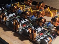
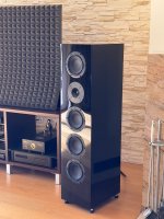
I was aiming for September and it worked! Two pairs of Elsinore ULD play beautifully. It is true that I still have the final finish of the front and walls in my pair, but the second pair, which was varnished by the professional, is fully ready. Just wipe off the dust and fingerprints after mounting the speakers 🙂
And the impression from the first moments of listening? Better, tighter bass. So bouncy. And a cleaner, dynamic midrange. And a unique way to build a very precise stereo image. I like it very much. Yes, Purifi is doing some serious work. There is a joy to listen to. I'm very happy.
Thank you Joe.
PS. There is still work to be done on the third and fourth pair. MFC version. The ELSINORE inscription will be stuck under the front. First I have to correct the letter N 🙂
Attachments
-
 2.jpeg199.8 KB · Views: 233
 -
 3.jpeg162.4 KB · Views: 216
 -
 4.jpeg166 KB · Views: 208
 -
 5.jpeg171.2 KB · Views: 197
 -
 8.jpeg140.1 KB · Views: 204
 -
 9.jpeg129.9 KB · Views: 220
 -
 11.jpeg184.9 KB · Views: 234
 -
 12.jpeg234.2 KB · Views: 244
 -
 13.jpeg201.8 KB · Views: 228
 -
 15.jpeg175.2 KB · Views: 231
 -
 16.jpeg87.7 KB · Views: 230
 -
 17.jpeg136.1 KB · Views: 249
 -
 18.jpeg208.5 KB · Views: 267
 -
 19.jpeg176.8 KB · Views: 269
 -
 20.jpeg395.3 KB · Views: 267
 -
 21.jpeg103.2 KB · Views: 249
 -
 22.jpeg165.4 KB · Views: 244
 -
 23.jpeg327.3 KB · Views: 234
JayBar,
Congratulations! 🙂 Your speakers look great. Impressive. I’m sure they sound a million dollars too.
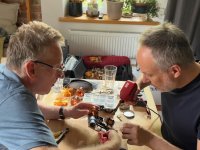
After hearing some of my favourite tracks on the Mark 6, what I knew already was really hammered home. I was missing a lot of mid range and bass with my Focal 918’s in my very poor acoustic room. I just had to get my hands on a pair of the Elisnore’s. The only issue is my hands-on DIY skills and tools are limited, so I’ve had to work with others to get my pair built.
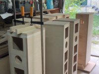
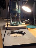
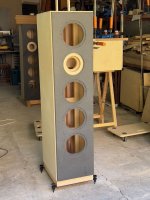
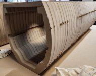
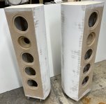
Fast forward 6 months and my Elisnore’s are about two weeks away from competition. Curved boxes.
Congratulations! 🙂 Your speakers look great. Impressive. I’m sure they sound a million dollars too.
After hearing some of my favourite tracks on the Mark 6, what I knew already was really hammered home. I was missing a lot of mid range and bass with my Focal 918’s in my very poor acoustic room. I just had to get my hands on a pair of the Elisnore’s. The only issue is my hands-on DIY skills and tools are limited, so I’ve had to work with others to get my pair built.
Fast forward 6 months and my Elisnore’s are about two weeks away from competition. Curved boxes.
Alfebear,
Any build pics? 🙂
Good luck and hope you can get the speakers up and running very soon.
Any build pics? 🙂
Good luck and hope you can get the speakers up and running very soon.
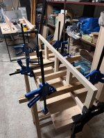
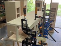
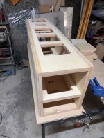
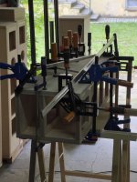
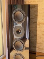
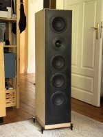
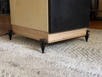
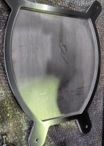
Hi, a few pictures.
Such a fun project.
Unlike some of you that are serial DIY builders that like to move between a variety of speakers, I hope that the Elsinore ULD‘s will be my sole main speaker for years to come.
This approach has led me to going a bit overboard e.g. sunken stainless steel base plates 😉
The internal volume of my curved boxes are identical to the Mark 6 boxes.
I’ll post a few more pics, once everything is in place and I’ve had time to listen to music and appreciate the whole package.
I was a bit reluctant to post earlier, as this tread appeared to me to move away from the Elsinore‘s and general DIY education, project excitement and the community of DIY audio.
For someone getting into DIY audio, whether building themselves or working with others who references a specific speaker DIY threads, it would be great if every now and then, the thread is steered back to the core DIY project. My opinion only. Reading about the Purifi option with the Elsinore in this tread in Nov 21 is what enticed me to seek out someone with the Mark 6 version.
Happy to share feedback on the sound soon.
cheers,
andrew
Attachments
- Home
- Loudspeakers
- Multi-Way
- The "Elsinore Project" Thread