why would you expect a difference ?Hello All,
“Just For Fun”
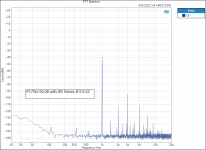
This morning I did some measurements on a Scanspeak P17WJ 00 08 driver with and without a L2 R2 coil model calculated 2 Resistor 2 Capacitor Zobel.
I used this driver and Zobel thinking that I have not observed any one with strong positive feelings about the model or driver on this thread. I am keeping the resistor and capacitor values under my hat so no one will call this a design or a competition.
The source amplifier is a Audio Precision APx 1701 with a sense resistor included.
There was no measured current distortion difference with or without the Zobel.
Note the reduction in impedance and impedance phase angle with the Zobel included.
View attachment 1089304View attachment 1089305View attachment 1089306View attachment 1089307
Thanks DT
The amplifier output voltage was 2 V RMS

Hello,why would you expect a difference ?
Personally I would not expect to see a difference, if fact I would be surprised if there was a difference .
I have see others post here that the amplifier may/will distort with the increasing inductive impedance load. Recall all that "unstable impedance" kind of talk.
Thanks DT
hello DT,
Me neither. the Zobel is a linear circuit shunted with the driver which draws the same nonlinear current irrespective of the Zobel. The Zobel draw some fundamental current but as your impedance graphs show then the current at 1kHz is very low.
If the amp is really bad then the load impedance phase change may affect its distortion.
By adding a series resistor between the amp and driver the effect of current drive can be mimicked partly. So e.g. add 8 ohms and increase the voltage to drive the same fundamental current. Then I would expect a reduction in the current distortion to to the increased load impedance seen by the voice coil.
Cheers,
Lars
The traces are the same.It hard to really see whats going on in the distortion graph. Colors are deceivingly similar (to me). The magenta trace hides the blue, but to what extent is not easy to know.
//
While the analyzer was running I toggled between the traces they are the same, same with no difference. I guess that the point was that one plot completely covers the other.
Colors are different for me. I am red green color blind. For stockcharts.com I can see purple for down and gold for up. Red and green are very similar shades of gray.
Thanks DT
When I do this again I will plot two separate plots, one with Zobel and one without.
Hello Lars and All,hello DT,
Me neither. the Zobel is a linear circuit shunted with the driver which draws the same nonlinear current irrespective of the Zobel. The Zobel draw some fundamental current but as your impedance graphs show then the current at 1kHz is very low.
If the amp is really bad then the load impedance phase change may affect its distortion.
By adding a series resistor between the amp and driver the effect of current drive can be mimicked partly. So e.g. add 8 ohms and increase the voltage to drive the same fundamental current. Then I would expect a reduction in the current distortion to to the increased load impedance seen by the voice coil.
Cheers,
Lars
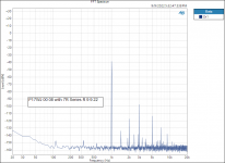
I had a bag of 7R Mills resistors handy, same ones used in the previous Zobel.
The Harmonic Distortion peaks are maybe reduced by 2dB's with the 7R resistor in series with the driver. The voltage across the sensing resistor was adjusted to be equal with and without the 7R resistor in place. (equal current)
Not much of a difference to my view.
Thanks DT
Attachments
It doesn't seem you used a 2 tones test. Try again it with a (loud) bass note playing simultaniously. That was the proposition. The cone needs to move!
Thanks!The traces are the same.
While the analyzer was running I toggled between the traces they are the same, same with no difference. I guess that the point was that one plot completely covers the other.
Colors are different for me. I am red green color blind. For stockcharts.com I can see purple for down and gold for up. Red and green are very similar shades of gray.
Thanks DT
When I do this again I will plot two separate plots, one with Zobel and one without.
What is probably best is publishing 2 version so both contenders can be on top.
How is orange for you?
//
So if i understand correct , the higher the impedance as seen by the driver, the lower the current it produces, thus the lower its distortion. Is this correct?JanRSmith, edit time over, and answer to your question was left out due to jargon.. 😀
It doesn't matter which name the amplifier has, acoustic distortion is reduced by reducing distortion current. Most distortion current originates from the driver, amplifier distortion is usually at least magnitude lower, THD 0,1% vs. 0,01% or better. Thus it makes sense to reduce distortion by driver. Read on Purifi articles and tech notes on their site for quick overview on the subject. And remember THD does not correlate with perceived sound quality, here the Purifi writings give some more ideas what is more audible and makes for better sound and its usually mid frequency problem. Woofer playgin low frequencies with quite some excursion makes distortion happen all of its bandwidth, even beyond low pass in active setup for example.
Its easy to evaluate what the distortion current originates from driver is by inspecting the circuit from drivers perspective, thinking driver as voltage source and what load impedance it has to get the current. Power amplifier is part of the circuit and as such part of the impedance. If its a voltage amp its almost a shortcircuit with its very low output impedance.
Oops, did not see later replies when answering. Answers thus geven. In simple terms series impedance helpt in reducing driver produced current distortion. Parallel (shunt) impedances do not.
But such series resistor also waste energy so that one need to up on the volume control. So to retain the same SPL level, i.e. the same amount of current/voltage must pass the voice coil - and we are back on the same situation - except for heating up a resistor ;-)
//
//
And altering the Qtc value of the system...But such series resistor also waste energy so that one need to up on the volume control. So to retain the same SPL level, i.e. the same amount of current/voltage must pass the voice coil - and we are back on the same situation - except for heating up a resistor ;-)
//
Very interesting some of the posts recently. I have been a bit incognito the last few days. I know that some of you are aware I have a son who is severely mentally ill, but there are now signs that better days are ahead, primarily because he now does not reject help. He is facing what he's got and it starts with S. We are wading through an incredibly difficult application for a Disability Support Pension. It is a very time-consuming process because they only give it to those who deserve it, but there is no doubt that he will get it and that will be a huge relief.
Now back to business:
Please note that this is the Elsinore thread and is mainly here to assist builders and indeed DIY'ers in helping each other.
So whatever I post will be with that view in mind, but I like what I am seeing in the new posts. Some are more hands-on and that is the spirit!
So maybe I should do a series of posts, like starting part one, etc.
KISS = Keep It Simple Stupid.
So I need to be strict and make this out about the philosophy behind the design. What are the weaknesses in design and what are the priorities because another designer may choose ones that are totally different?
MAKE A RECORD: A series of post...
That way I can give links in the future to anybody who asks and I don't have to do it all over again. Just look up this link and you will know the story.
Part One... coming soon. It will talk about the mechanism of the distortion that current drive avoids and why it works that way. Why the Elsinore design is at least, I hope, a valiant effort to get the lowest distortion from the loudspeaker when using a voltage source because the world is not going over to current-drive (although it does have a place in a closed system like active speakers).
Please note this is about a journey and background to why the Elsinores turned out the way they did. Like having an effective 100L internal volume because I like open baffle midrange loudspeakers, but I wanted a solution and went 2.5-Way because I wanted a large internal volume so that no sound comes back through the cone, just like my treasured open baffle midrange speakers did in the past. The practicality of a box but getting as much benefit as possible - big internal volume.
There is a heap of that stuff in the Elsinore design, but I will concentrate more on the nature of current and why it should not be it should always be considered by the speaker designer, but to be honest, most of them don't do that.
I'm not sure an ideal resistor really changes Q as a pure resistor has no reactive effect.And altering the Qtc value of the system...
Q is basically the bell shape (width and height) of a resonance.
Someone with sufficient skills (not me) in an electronic simulator could show all this easily.
//
System Q, needs to be considered as well, its all in the same system, and everything needs to be considered as a system. Reducing distortion current with series impedance might be possible or not, depending on application.
Those who are concerned about bass box Q, analyze series inductor instead of resistor 😉 how about applying this for mid only, separate bass box? What Q actually is?😉
what about cone resonance, how to tame cone resonance peak, which one to use series or parallel notch? 🙂 how about active system, would system with DSP benefit also from few passive components instead of straight wire? 🙂
Many ways to apply the knowledge on our own systems.
Yeah active is far more flexible, but active does not manipulate impedance and infact has worst possible driver distortion due to this, if you think it through. Just reap benefits of both, impedance manipulation with one or two passive parts, frequency response manipulation with DSP.
edit.
Main message is of course that the more there is excursion on a driver the more there is this distortion current, so the distortion current can be reduced also by reducing excursion, or use better quality driver with less non-linearities. Acoustic low pass does also something similar, lowpasses distortion products as well. But still there is opportunity to further reduce distortion current with the impedance. Many ways, just something good to know and consider while designing loudspeakers.
Last edited:
Since (most) amps are voltage amplifiers, I think any distortion from the amp should be visible on the voltage, so just measuring the voltage on the amp output should reveal any distortion from the amp, just as in normal amp distortion measurements. ...
I would like to make the case for doing both voltage distortion, but then also current distortion which hardly anybody measures, but you will see a number of examples already posted,
We must use an actual driver for these measurements, not resistors nor
I am hoping that the Vifa P17WJ-00-08 will become the standard driver to use.
I have a pair and they have a very well-controlled flaw. And the ones I have measured have been very consistent. I believe that Scan-Speak has brought out more of them, not sure what the number is limited to.
Keep in mind, if you had the perfect driver, the measured distortion on the voltage side would show up as identical distortion on the current side.
But to set the record clear, with a perfect load and say 1% voltage distortion, that will also show up on the current side as 1% distortion.
But what if you now connect an imperfect driver? The same 1% distortion will show up on the current side plus there will be even more caused by "EMF derived distortion" - as Esa Merilainen calls it. This is not a guess.
If you can reduce that distortion, that would be admirable.
Of course, with current drive you can reduce that distortion. In fact, you will go some way to prevent distortion.
But what if you stick to a voltage source? Most of us do. Voltage drive is here to stay!
Find ways to prevent this distortion as much as possible. That is what I try to do. Find ways!
This is about making/designing loudspeakers that work with a voltage source and ideally have the same low distortion as a current source. A mighty challenge indeed.
To do something about it, we need to understand the mechanism, and why does a current source prevent distortion compared to a voltage source?
That's ground zero, understanding that mechanism. You don't need complicated maths, just good sense, and then we can make no progress
Sometimes we have to resort to thought experiments. I have a good one...
So, adding a resistor in parallel to the driver will most likely increase the amp distortion, and do nothing to lower driver distortion.
It is not that simple. The voltage of the amplifier does not tell us exactly what we are listening to, but the current does.
Again remember we need a real driver to do this, so please read on...
What are we looking at below?
This is 2 kHz sine wave. The voltage is yellow and maroon is the current.
How do we get this on our two-channel scope?
So we clearly have two sinewaves at the same time, one is the voltage, but also there is a delayed 30° current phase angle sinewave caused by the inductance. The amplifier has reacted to our real driver, not a dummy load.
Which of these two sinewaves are you listening to? You cannot be listening to two sinewaves, only one. The time difference precludes it.
Common sense tells us that at 2KHz we are listening to the delayed 2KHz and that means what?
You are listening to the current of the amplifier!
Now comes the test that hammers this hone:
Put both through an audio analyser and measure the distortion in both and compare - and there will be more distortion on the current side of the amplifier than the voltage side.
Remember: We need to use a real speaker as the load!
So let us do a thought experiment (because I like them).
If the driver is 8 Ohm and you know and have measured the current side distortion (there are plenty of online examples where this is done), and now because you have a voltage source that can do anything, what if we make it look like this:
There will be about ten times the current going through our parallel resistor compared to the driver. But the 8 Ohm driver will likely have an impedance that looks like this:
Whilst the above is simulated, there is a major issue going on here. If you combine low frequencies with excursion whilst reproducing frequencies well up to sensitive frequencies, you can see that the impedance is not stable. This impedance modulation causes current modulations in the amplifier supplying the current.
If the impedance is not stable, then the current of the amplifier is not stable.
It is that simple. You cannot divorce the current from the force BLi - to be blunt, as far as the driver is concerned, the voltage doesn't even enter into the 'equation' and yes, there are equations.
I think I came across Lars saying pretty much the same thing, right?
In the Elsinores the above negative effect is majorly reduced by the fact that below 500 Hertz the excursions required to move X amount of volume, is say 10mm peak to peak and that is now reduced to 2,5mm peak-to-peak. Now for the same SPL we have made the impedance seen by the amplifier reduced by 75% and that is not the only thing. Add a carefully calculated series inductor and percentage-wise you can reduce even further, sometimes as much as 5:1 at 1KHz and as much as >10:1 at 10KHz.
But that is another topic. It is also related to what series resistors do, but this is a bit more wily.
We can reduce "EMF derived distortion" as Esa Merilainen calls it. I call it plain current distortion of the amplifier and we need to control it. This is both audible and measurable, electrically and acoustically.
Now, what about our thought experiment above?
Note that the amplifier now produces ten times the current. It a lot of current. It will get very hot, but hey this is a thought experiment.
Will there be a reduction in the current distortion of the amplifier? Now connect up our audio analyser... interesting...
Further proof below: Look what has happened to the current phase angle? Now isn't that interesting, they almost line up perfectly in time. Note that the maroon is the total current of the amplifier. Try to induce driver EMF problems now.
Not only does this trick about parallel resistor to tame the current of the amplifier, indeed we know that a number of famous speaker designers and brands do this. When I visited Ulrik Schmidt I brought this up and he admitted to me he also knows names that did use it. Hush-hush.
Often when you see the impedance plot of these speakers, you can spot it. Did anybody say Wilson... ahem?
I do not use resistors like that.
And neither does my long-time friend and designer Brad Serhan (Serhan+Swift).
But what about using a reasonable resistor:
The resistor trick can be tried with any speaker that has 8 Ohm speakers and amplifier drive 4 Ohm, then add an 8 Ohm resistor. But don't bother doing it with the Elsinores where my solution(s) is more elegant than that. Not sledgehammer solutions.
I have noted something curious, numerous online experiments and comments about a reduction in specially odd-order distortion artifacts. Both Esa and I have pointed out that this kind of EMF-induced distortion of the current is actually feeding back on itself. In other words, there are ongoing cycles and time smearing going on.
I would like others to comment on this. Do the measured odd-order issues point to time smearing?
Again, please note that the above comments have to do with the Elsinores and not wider theories. I am trying to keep the thread on topic.
This will influence my replies from here on.
But everything would be solved if we had the perfect driver. Then there would be no added distortion even with voltage drive.
There was no measured current distortion difference with or without the Zobel.
Note the reduction in impedance and impedance phase angle with the Zobel included.
I am not that surprised.
So it should really be readily measurable in the acoustic domain if done right?
Like: Meas1=Voltage drive, Meas2=current drive - everything else equal - look at the difference distortion wise!!.. kind of comparison.
But with a FR penalty at resonances...
OK. But not if it looks like this:
Please let me explain something that is tricky to get across. The above is an actual measurement using Clio 7 some years back. It behaved like a sealed box but it was an aperiodic vent. Single impedance peak. Treat it like it was a sealed box.
Blue is the impedance, Red is the current phase angle.
Now here is a thought, make the amplifier produce the same current at all frequencies, even LF.
Guess what? This is really neat.
You can use current drive and get no change in FR near resonance.
Even the crossover gets be locked in, no matter what the source impedance.
Now think about this, and this goes back a long way with me, that it is a myth that you need a near zero source impedance and not blow the alignment of the box. In fact, this goes way back to Neville Thiele around 1960.
That the damping at the motional peak and its surrounds can be controlled by current versus frequency.
In fact, this was Thiele's method of calculation. You could use voltage or current and get the same result. But you would get the same current versus frequency curve with either and hence fully damped.
With current you measure the voltage, with voltage you measure current. Way back in the 80's I did work for a company called Jaycar and did their testing, even wrote a Basic program to help me do the work on an Amiga 500. Ah, those were the days. I did many such tests over the years on samples they sent me pre-importing. I used both tests and got to figure out something really neat.
But I have never seen any textbook actually say this. There is a precise frequency vs current curve and if you can replicate that (and the above measurement does), then Qes is not related to the output impedance of the amplifier. Make the impedance look like the above and you have ensured that the current through the voice coil is no longer dependent on the amplifier. At the right frequency, pick one near Fs and it will see the correct current always.
Either you get it or you don't.
And yes, it is applied in the Elsinores, but is fractionally compromised at extreme LF because it is vented. But only to the extent of less power handling around 20 Hertz, which already has plenty to start with.
...
But what if you now connect an imperfect driver? The same 1% distortion will show up on the current side plus there will be even more caused by "EMF derived distortion" - as Esa Merilainen calls it. This is not a guess.
If you can reduce that distortion, that would be admirable.
Of course, with current drive you can reduce that distortion. In fact, you will go some way to prevent distortion.
...
Hi Joe, I'm not sure if you read all posts from past few days? the discussion has been about this, back EMF distortion, distortion generated by the driver. Its easily seen, analyzed and reduced just by looking the circuit from driver side. Increase driver load impedance to reduce the distortion current.
- Home
- Loudspeakers
- Multi-Way
- The "Elsinore Project" Thread