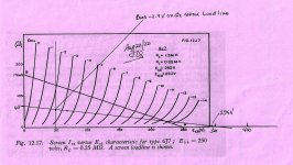
So here is the slide missing from last nights entree. A plot of a 470K loadline on the 6C6/6J7 screen curves.I made an error here, not sure why, the bias voltage should be 0.86 mA x 2K, that being 1.72V,
There is also one slide missing, I'll stuff that in later. 😱
At the 2.4V bias reported in posts 31 & 39 the screen would be at 50V. The result puts the 75K loadline in
the steepest position possible while not shortening the possible voltage swing available. When the effect of
the following AC load of the 2A3 grid resister is about the limit.
A better condition would be Rl of 100K & Rg2 of 400K. 🙂
Think I may have done some of the preliminary on that while looking at the G2 part of the design process.Also, if you're interested, you could touch on the topic of G1-G2 mu and the "inner triode" of a pentode.
I'll put something more formal together & post in a few daze. Kinda busy here with manual labor, gotta
limit time on DIY.
Attachments

Yep, ~2k Rp, ~15mA will drive the 2A3 well.What about a 6v6 driving the 2a3? I ask because I've got some old engraved coke bottle sylvania begging for some electricity.
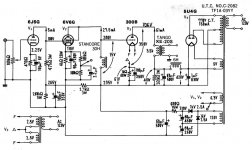
3 stage DC amplifier well recieved for 30 years (attached), adjust for 2A3.
Note: some values on the schematic dont add up, but good for illustration.
Attachments
Last edited:
IIRC, Olson was building PP amplifiers.This is the approach I considered. 12HL7 triode-connected driver, at 30 mA cathode current and 250 plate volts. Amplification factor is 30-40 (thanks to Smoking Amp for this recommendation). Samples of this tube selected on curve tracer may be very linear. The drawbacks are very high Gm (oscillation!) and driver's idle current half the output current. The advantages are possibility of using currently produced ITs and very low driver output impedance.
High current drivers for DHTs have been advocated by such eminent designers as Sakuma and Olson. However, I believe that 30 mA driver for 2A3 is a bit of overkill. Whether it will result in better sound comparing to lower current drivers should be determined experimentally.
Sakuma designs never made much sense to me, he listened in mono with a lowther driver fitted to a wine barrel ?? (ref: pic from SP mag).
I think the OP's considerations are 'good enough'. Sure, use D3a choke loaded DC to 2A3 - you might prefer the 6SL7 😎
Last edited:
Member
Joined 2009
Paid Member
I always interpreted the point of Sakuma's designs as being his personal journey - he had some good ideas. Firstly, he tended to use simple topologies which allowed him to learn and get a feel for what does and does not produce results he liked where otherwise there might have been too many variables. Many of the 2A3 designs of this thread are simple topologies.
He also preferred to use lots of iron, again this keeps things simple and he stuck to one brand and a fairly narrow range of transformers so that he could be familiar with what to expect from them.
But most importantly, he was designing for himself, to produce a sound that he wanted and was never a slave to influencers. I believe the take away he wanted people interested in his work to receive was that they pursue their own sound.
I also listen mostly in mono, I have many good reasons for this but one of them is that I no longer fight with the room or fuss over 'imaging' and other stereo related effects and as such find it to be a much more natural listening experience. It's a big topic by itself but the key is single speaker for mono, not mono through a pair of speakers. Sakuma didn’t have a quiet and controlled listening room, he had his restaurant, his music was played in a ‘living’ environment which is how I think of my house where I listen.
p.s. I have this niggling thought that high transconductance tubes don't sound as 'nice' as the pre-space era glass?
Last edited:
I also listen mostly in mono
Bigun - you touch a very interesting and controversial subject here: is stereo necessary? I've read an opinion that stereo was, and is, a big fraud perpetrated by recording industry. The person who expressed this opinion didn't elaborate, but I believe it was about reproduction chain quality. Mono, when done at high resolution and without tampering (= down mixing from multichannel sources), like Mercury Living Presence, RCA, or Belock Everest, has a lot of spacial cuies. Low resolution strips the spacial information, but with two channels you have 3d on the cheap. So, instead of pursuing expensive high resolution repro chain, the industry moved on the path of cheap lo-rez stereo.
Anyone can get proof that binaural hearing is not absolutely necessary for spatial location of sound source. With one ear closed, there is no problem locating direction to sound source.
Like you, I like listening in mono. Piano sounds so natural through a good amplifier and a single Neo-8s. You can hear lows, mids, and highs coming from different directions. You can easily perceive recording engineers' tampering as piano and pianissimo come from closer distances than forte and fortissimo.
Sorry for straying from topic, but no sorry since this is a very important issue for good sound reproduction.
Last edited:
I only have one ear that can hear, and it is not real good at that.
When it first happend, my other ear suddenly went dead except for the ringing, which remains to this day.
I used to walk across the room in front of the two speakers about 3 or 6 feet away, walking parallel to the plane of those two stereo speakers.
With only 1 ear, I suddenly was Very Sensitive to the comb filter effect, because many stereo recordings have identical sounds in the left and right channels (in an attempt by the recording studio to 'create' a pseudo center channel). That effect almost causes your head to quickly turn and almost hurt your neck as you walk.
I often listen to just one channel (Left only, or Right only). That is Not Stereo, but it also is Not Mono either.
But you would be surprised, because of the lack of comb filter effect, the lack of other cancellations, and the lower intermodulation; Versus just electrically combining the Left and Right channels using a pair of resistors.
And, if you really think you can properly locate a sound with only one ear . . . Think Again!
If you lose one of your ears, you have my sympathy.
In spite of having only one ear, I am able to enjoy listening to my many CDs.
Your Mileage May Vary.
I forgot to put this comment in my last post: Post # 86
If you want to learn about the issues and sound results of pseudo center channels, different recording miking techniques, production mixing, etc. . . .
. . . Then I recommend you get Either a stereo sound card that can do an XY display, Or a 2 channel analog oscilloscope that can do an XY display, Or a 2 channel digital oscilloscope that can do an XY display.
Then, for every CD, Vinyl, or FM music you listen too, be sure to monitor the Left and Right channels with your XY display device that is mentioned above.
You will learn a lot. Have Fun!
Just My Opinion and My Experience
While we can argue on merits of transformer vs. capacitor as coupling device, one disadvantage of RC-coupling is not debatable: low available driver plate voltage causing excessive distortion.
Radiotron RC-coupled amplifier charts show that maximum output signal level (at 5% THD) roughly doubles with doubling of B+ voltage. With 300 V B+ in a 2A3 SET, a 6SN7 driver can deliver 80 V peak output volts, which is more than the required 45 V peak. However, one has to accept about 3% THD in the driver stage. Note that plate voltage of 6SN7 is only about half of B+.
With transformer coupling, driver's plate voltage is close to B+. Thus, the output swing at 5% THD is twice as that of RC-coupled stage., making the driver much more linear.
Another unquestionable advantage of transformer coupling is increased linearity due to horizontal load line. Although same effect can be achieved by CCS loading, a CCS is a complication, and a problem-ridden device upon closer look.
Member
Joined 2009
Paid Member
Linear triode drivers for 2A3
Setting aside very high transconductance triode-connected pentodes such as D3a or 12HL7, here is my list of most linear triode drivers for 2A3. All have 6 mA quiescent current, which is neither too low, nor excessive for the purpose. All have Rp of 10-11 K and will work with a 1:1 interstage transformer.
1. 56/76/6P5G. Mu=13.5, Gm=1.4 mA/V. My preferred choice, if not a bit low amplification factor, which would require a little boost in input transformer (A-20 configured to 1:1.3) or interstage transformer (A-18 with parallel secondaries, 1:1.2).
2. Triode-connected 57/6C6/6J7G. Mu=20, Gm=2 ma/V. This has better linearity than 6SN7 or 6J5, and lesser grid-to-plate capacitance.
3. 53/6A6/6N7G. Mu=30, Gm=3 mA/V. Better linearity than other medium mu triodes like 6N1P or 12AY7.
Anything else?
2C22?
I like 6N30P (DR) too, but it's also a bit unsensitive.
6C45P.
I usually use high gm -trioded- pentodes as driver: D3a/E280F/E810F/E180F, C3g, C3m.
I like 6N30P (DR) too, but it's also a bit unsensitive.
6C45P.
I usually use high gm -trioded- pentodes as driver: D3a/E280F/E810F/E180F, C3g, C3m.
DIY interstage transformer
A good 1:1 interstage transformer is easy to make because it can be wound bifilar. One problem of bifilar transformer is high capacitance between primary and secondary. This can be reduced by spacing wires with polyester monofilament of the same diameter.
 The thinnest available is 0.1 mm, so it can be used with 0.1 mm wire. Wind with 1 wire thick layers and place your favorite insulation (mine is Teflon film) between layers. Use your favorite type of core (mine is permalloy or amorphous). Core gap is adjusted for best compromise between inductance and DC current.
Another problem of a bifilar transformer is that it can be connected in only one way. Flipping secondary ends will result in severe degradation of high frequency response.
A good 1:1 interstage transformer is easy to make because it can be wound bifilar. One problem of bifilar transformer is high capacitance between primary and secondary. This can be reduced by spacing wires with polyester monofilament of the same diameter.
Another problem of a bifilar transformer is that it can be connected in only one way. Flipping secondary ends will result in severe degradation of high frequency response.
All excellent choices for high current low Rp drivers suitable for modern interstage transformers. 6H30 and 6S45P are somewhat limited by low maximum plate voltage.2C22?
I like 6N30P (DR) too, but it's also a bit unsensitive.
6C45P.
I usually use high gm -trioded- pentodes as driver: D3a/E280F/E810F/E180F, C3g, C3m.
sser2,
P#88
No, the beautiful sounding WE212E amplifier I heard used a 6SN7 driver (for many of you that is a sacrilidge), with several resistors in series for the 6SN7 plate load (to withstand the high voltage). That can be a very high resistance, approaching a current source.
1200V and the multiple series resistor plate load gave the 6SN7 plenty of volts (it is rated for up to 1500V peak pulse, so it does not arc over when the amplifier 1200V B+ powers up before the filament is warm).
So, RC coupling is OK after all . . .
(if you know where to find a good sounding 2000V coupling capacitor).
P#89
No, not a horizontal load line. An interstage transformer does not have a flat load line: Inductive reactance at low frequencies; Capacitive reactance at high frequencies. But Beautiful at mid-range frequencies.
P#93
Nice idea for a 1:1 interstage transformer. But . . .
The wires are not as tightly coupled, the one major advantage of bifilar winding techniques.
And, as you properly mentioned, an audio bifilar transformer should never have the ends swapped.
As properly built, and used as intended you get the closest coupling between the primary and the secondary.
And . . . you get the capacitive coupling between bifilar primary and secondary.
Afraid of capacitor coupling?
Then check out all the commercial recordings (and perhaps even your own recordings) that use RC coupling somewhere in the recording, production, and playback equipment (and any solid state equipment along the way of those equipments almost certainly uses electrolytic coupling capacitors). Throw those recordings out, they sound horrible with that capacitor coupling (No, I am not serious, do not throw those recordings out).
And, with microphones, mic preamps, etc. there are almost certainly transformers there, but they are anything but bifilar (if they are 1:1, they likely have a shield between the layers).
Bigun,
P#90
No, blocking distortion with RC coupling is not a problem on a 2A3 amplifier if you use 104db/Watt/Meter speakers, and for even more moderate sensitivity speakers. You get the idea. Think of the total system, not just the amplifier.
The above are all just my opinions.
. . . Seriously, enjoy the music!
Last edited:
In my earlier post I was questioning the need / advantage of using an input transformer, not an interstage transformer. I don't doubt that the advantages you listed, which I'm not technically oriented enough to dispute, are real. It just seemed like most of them offered little to no practical / audible advantage under most circumstances.While we can argue on merits of transformer vs. capacitor as coupling device, one disadvantage of RC-coupling is not debatable: low available driver plate voltage causing excessive distortion.
Radiotron RC-coupled amplifier charts show that maximum output signal level (at 5% THD) roughly doubles with doubling of B+ voltage. With 300 V B+ in a 2A3 SET, a 6SN7 driver can deliver 80 V peak output volts, which is more than the required 45 V peak. However, one has to accept about 3% THD in the driver stage. Note that plate voltage of 6SN7 is only about half of B+.
With transformer coupling, driver's plate voltage is close to B+. Thus, the output swing at 5% THD is twice as that of RC-coupled stage., making the driver much more linear.
Interstage transformers may offer technical advantages too. And yet, very few amps seem to use them. I suspect that's because many designers don't consider the cost / benefit ratio to be advantageous. If they're not being produced commercially, or if the cost is prohibitive, there must not be much demand. I suspect that most people are not really interested in trying to build their own interstage transformers.
You point out that an interstage transformer will produce twice the voltage swing, yet you acknowledge that RC coupling produces more swing than is really needed. The distortion may be lower, but it comes as a significantly higher cost, as long as the caps chosen are not outrageously priced. And, while the two distortion levels can be measured, are either of them audible?
I know the more technically oriented, engineering types, spend a lot of time and energy trying to minimize distortion. Which is fine, nothing wrong with low distortion, but from a practical / audible perspective its importance can sometimes be overestimated.
A few years ago, I bought a cheap SS Chinese preamp purely because it had remote control for volume with mute and channel switching. Totally for convenience, in other words.
I had to laugh when I read a review on ASR which said it had way too much distortion - 0.0032%! The unit they recommended as an alternative cost almost 3x more and measured only 0.0005%. They conveniently ignored the fact that nobody can actually hear the difference.
Not only that, but the "better" unit was a "passive preamp", so not really a preamp at all, just a volume control with the same switching abilities. Geez, you mean a volume control has less distortion than something that involves an actual circuit? Who would've guessed?
Obviously, many of us prefer tube amps even though they produce much higher levels of distortion. But how high is too high?
I'm not a measurements guy but, as I understand it, when equipment is used to measure distortion, it's generally done at a single, steady, fixed frequency. It turns out that people are also more sensitive to distortion when a single frequency is used. But distortion, when listening to music, has to be quite high in order for a person to hear it.
Here's a summary, from an article I read, of people's audible perception of distortion:
" . . . our tests indicated that very small amounts of distortion (0.15 per cent) are perceptible if the program material is sufficiently simple—for example, a single pure, steady tone. Mixing two tones dramatically raised the threshold of perception to over 2 per cent. Three simultaneous tones, representing increasingly complex program material, resulted in a perception level of a surprising 4 per cent. With normally complex music, it was necessary to increase distortion to a full 6 per cent before it became just [barely] perceptible. . . . at 6 per cent we just began to detect a "strained" quality in the singer's voice. However, even at 6 per cent, distortion was not evident on the percussive instruments. It was only at 12 per cent that distortion began to affect the sound of the guitar and cymbals. Higher [than 12%] distortion levels caused an obvious "fuzziness" in the sound. To test the relationship of volume level to the ear's ability to detect distortion, we played the music at a very loud level with peaks exceeding 100 dB. There was no difference: distortion was again just barely audible at 12 per cent."
BTW, and FWIW, the listeners in that test were well known professional audio writers and equipment reviewers from some elite high end audio magazines. So they're likely used to listening more critically than most folks. Since I don't read those magazines I wasn't familiar with most of them. The only name I recognized was Julian Hirsch.
Well, I see that someone has questioned this in a later post.Another unquestionable advantage of transformer coupling is increased linearity due to horizontal load line. Although same effect can be achieved by CCS loading, a CCS is a complication, and a problem-ridden device upon closer look.
I've been using inexpensive Hammond 156C plate chokes recently. Perhaps I'm misinformed, but I was under the impression that they also affect the linearity and drive in at least somewhat of the same way as an interstage, though perhaps to a lesser degree. Please correct me if I'm wrong.
These little 150H Hammonds are cheap and can handle up to 8mA. I can't say that I've spent any time listening to them A-B'd vs a resistor load, and I have no way to measure them, but they seem to work well.
We seem to be on the same page when it comes to drivers.Linear triode drivers for 2A3
Setting aside very high transconductance triode-connected pentodes such as D3a or 12HL7, here is my list of most linear triode drivers for 2A3. All have 6 mA quiescent current, which is neither too low, nor excessive for the purpose. All have Rp of 10-11 K and will work with a 1:1 interstage transformer.
1. 56/76/6P5G. Mu=13.5, Gm=1.4 mA/V. My preferred choice, if not a bit low amplification factor, which would require a little boost in input transformer (A-20 configured to 1:1.3) or interstage transformer (A-18 with parallel secondaries, 1:1.2).
2. Triode-connected 57/6C6/6J7G. Mu=20, Gm=2 ma/V. This has better linearity than 6SN7 or 6J5, and lesser grid-to-plate capacitance.
3. 53/6A6/6N7G. Mu=30, Gm=3 mA/V. Better linearity than other medium mu triodes like 6N1P or 12AY7.
Anything else?
For my current SET breadboard experiment I started with 6A6s, which worked very well. I copied that input section from a Japanese 2A3 SET. I then started trying some 5 pin tubes. A couple of them didn't quite pan out but I've got some 76s in there at the moment and they sound good too.
I've got some 6 pin sockets on order so I can try some 6C6s, which I have in stock. And I've got several octals I want to try, including the 2C22s, which I use in a PP 6B4G amp I built years ago and recently updated a bit. I'll also be trying some 6SL7s.
I may even try the 26, which is what I used in my most recent build. If you use output tubes that don't require so much drive you have more options.
As for coupling, my current project uses neither interstage transformers nor cap coupling. I'm using direct coupling on this one. So far I'm really liking it.
6A3sUMMER:
I have no doubt that with 1,200 V B+ and high value plate load resistor, 6SN7 would be hard to beat distortion wise. But for 2A3 SET, would anyone go into trouble of adding a 1,200 V rail, even for a sonic benefit? By the KISS principle, one should use what one has, that is 250-300 V B+ of the output tube.
If a transformer has inductive reactance at low reproduced frequency, and capacitive reactance at high frequency, then maybe it is not so good of a transformer, or amplifier bandwidth is in excess of transformer capability. Low frequency inductive load means insufficient primary inductance; make more inductance, or limit low frequency, and the problem disappears. High frequency capacitive load means excessive winding capacitance; reduce winding capacitance, and the problem disappears. Choosing an interstage transformer, I would rather sacrifice low end performance (anyway, 100 Hz and lower is a job for a subwoofer, not the main speaker) for high frequency response beyond 20 kHz.
With bifilar wires at 0.1 mm separation, magnetic coupling between windings is still almost as tight as with notmal 0.01 mm separation (two layers of wire enamel). Extra separation may add a few mH to leakage inductace, but that's nothing compared to leakage inductance of a non-bifilar transformer.
Capacitive coupling is not as pervasive as one might think. Transistor circuits can be easily designed without coupling capacitors, and that' how it looks like when you examine schematics of transistor amplifiers and players. In my SCD-1 and NS999ES players, there is only one capacitor directly in the signal path - at the RCA output. In my Kenwood KD720 amplifier, there is only one series capacitor - at the input. Both can be avoided, as offset DC voltages are zero. So, I am not of the "mi ban fa" opinion, as Chinese say, which means "you cannot do anything about that". I avoid capacitors wherever possible.
sser2,
Of course if you have lots of $$$ or Euros, you can purchase a next-to-perfect interstage transformer.
But it is not simple, and not easy to build your own, so there goes the simple in KISS.
Using a subwoofer because a 2A3 amplifier that uses a less than perfect interstage transformer that has poor low frequency response is not a simple solution either.
If you use a given wire size to make a bifilar transformer that Also includes a dielectric wire spacer, the transformer laminations will have to be bigger, and the wire length longer too (you do want the same inducance, right?
Not to mention that a small amount of air spacing between the bifilar wires of dielectric constant = 1, may not have a large winding to winding capacitance, but replacing air with a modern dielectric material like polyester monofilament that has a large dielectric constant much much greater (dielectric constant >> than air), the polyester might create as much or more wire to wire capacitance. Point of diminishing returns.
You probably have not talked to the same studio production engineers that I have, they go in and replace those old coupling capacitors and electrolytic capacitors on their sound boards, etc.
And if we are going to get rid of electrolytic capacitors that are the signal path, then we need to replace all the B+ electrolytic caps, and all the bypass electrolytic caps. Perhaps battery B+ is best, but the circuit parameters change if you want to eliminate bypass caps in order to not have to find room for modern non-electrolytic caps.
It is real hard to do that with all those wonderful 1950s, 1960s, 1970s, and beyond recordings.
Who has a time machine to be able to go back and modify that equipment from decades ago?
I do hope after they get done, that they go back in time and bring some modern Acrylic paints for Monet to try.
Over 1000 years ago, the Chinese built resonator tubes of different lengths to build 'sound amplifiers'.
"You should make things as simple as possible, but no simpler" - Albert Einstein
Last edited:
Aren't we all trying to put together something really exceptional, something better than has been created before? If I accept that difference between RC and transformer coupling cannot be heard, and that with complex music distortion does not matter (in fact the opposite is true), am I not channeling myself into some kind of mediocre outcome? I understand the excitement of "I did it, and it works", but it is not why I am into this hobby.
I believe that every rational step to reduce distortion is a step in the right direction. It maybe incremental and not bringing about dramatically audible improvement per se, but many incremental steps will result in improvement.
I believe that every rational step to reduce distortion is a step in the right direction. It maybe incremental and not bringing about dramatically audible improvement per se, but many incremental steps will result in improvement.
The use of subwoofer with a 2A3 SET is not because of IT limitations. It is because reproduction of bass and mid-hi by the same driver causes intermodulation distortion in speaker.
- Home
- Amplifiers
- Tubes / Valves
- Developing a 2A3 SET