Here's a very simple circuit which sounds good to me. I put in 2 sockets - one octal and one 9 pin and the same circuit works for 6SN7 and E180CC depending how much gain you need in the first stage.


That is a lot of hardware & expense ($$$) to accomplish very little, Basically just something to look at, 🙂 👎Non of them tolerate DC current.
My examples applies to line level (1:2 or 1:4) SUT and common 1:1 IT as anode load of first tube.
Sample:
View attachment 1082387

Right.That is a lot of hardware & expense ($$$) to accomplish very little, Basically just something to look at, 🙂 👎
The SUT, DHT driver tube and IT at least as cost, than 2A3 and OPT ..... but this driver developed for larger SE power stages, so there is only a sample design.
Yes, I'm well aware of turns ratio squared as the multiplier for drive impedance; 100,000 ohm was a colloquial expression - it may as well be 100k.Low -3 dB point of IT in this circuit is 25-28 Hz. The transformer-coupled 57 will present 40 K impedance to 2A3 grid, not 100 K.
Input transformer has other benefits: isolation from ground loops, possibility of balanced input allowing longer interconnect, and possibility to tweak overall gain.
The best bias for 2A3 is also from permanently wired battery. Six 9 V batteries. BTW, I am not claiming that this is capacitor-free design. Last filter capacitor is in the signal path in any SE amplifier.
Consider a 2k Rp type driver with mu 50+ that can operate into 1:1 IT.. you have better LF, HF, a less compromised transformer (build), and 20 times lower drive impedance, ie. 2k ohm.
1:4 input and 2:1 interstage would be much better, depending on other things which are not considered like the source to the amplifier, but also unneccesary, I dont see the advantage (in any meaningful way) of an input or interstage transformer when you need only need 90vp-p for full output at the 2A3 grid.
Last edited:
This is the approach I considered. 12HL7 triode-connected driver, at 30 mA cathode current and 250 plate volts. Amplification factor is 30-40 (thanks to Smoking Amp for this recommendation). Samples of this tube selected on curve tracer may be very linear. The drawbacks are very high Gm (oscillation!) and driver's idle current half the output current. The advantages are possibility of using currently produced ITs and very low driver output impedance.Yes, I'm well aware of turns ratio squared as the multiplier for drive impedance; 100,000 ohm was a colloquial expression - it may as well be 100k.
Consider a 2k Rp type driver with mu 50+ that can operate into 1:1 IT.. you have better LF, HF, a less compromised transformer (build), and 20 times lower drive impedance, ie. 2k ohm.
1:4 input and 2:1 interstage would be much better, depending on other things which are not considered like the source to the amplifier, but also unneccesary, I dont see the advantage (in any meaningful way) of an input or interstage transformer when you need only need 90vp-p for full output at the 2A3 grid.
High current drivers for DHTs have been advocated by such eminent designers as Sakuma and Olson. However, I believe that 30 mA driver for 2A3 is a bit of overkill. Whether it will result in better sound comparing to lower current drivers should be determined experimentally.
As to whether or not input transformer is justified, the alternative is input capacitor. Pick your poison.
sser2,
The 3rd alternative is to purchase a CD player that has balanced outputs (I have one).
Then you do not need an input splitter transformer; and you do not need an input capacitor.
No poison here, unless you do not like balanced CD players and balanced amplifiers.
Same number of tubes.
For single ended amplifiers, why do you need an input capacitor?
Just purchase a good CD player that does not have significant DC offset from the L and R outputs.
For single ended with an input transformer, you can put the bias battery positive to the secondary output 'hot lead' and the battery negative lead to the input tube grid, then ground the other end of the secondary. It does not hurt to use a floating battery.
That works, ask me how I know?
Now, where did I put my soldering iron and my calendar schedule?
Last edited:
6A3sUMMER: one of my CD players (Sony SCD-1) has balanced out. But from its schematic, it adds an extra differential transistor stage, so I prefer the regular RCA output. I don't know about others, but all my CD players originally have output electrolyric capacitors. They are not necessary, since the OPA output has zero DC offset. They are added "just in case". I shorted these capacitors and connected outputs directly to autotransformer volume control. Works fine.sser2,
The 3rd alternative is to purchase a CD player that has balanced outputs (I have one).
Then you do not need an input splitter transformer; and you do not need an input capacitor.
No poison here, unless you do not like balanced CD players and balanced amplifiers.
Same number of tubes.
For single ended amplifiers, why do you need an input capacitor?
Just purchase a good CD player that does not have significant DC offset from the L and R outputs.
Now, where did I put my soldering iron and my calendar schedule?
My circuit requires either input transformer or input capacitor for a simple reason: input tube grid is at bias potential. Cathode bias would avoid this problem because grid is grounded. But cathode bias requires bypass capacitor, otherwise distortion and stage's output impedance will increase, and gain will decrease. I want to avoid this conundrum, hence fixed bias that requires either input transformer or input capacitor. Transformer is my preferred choice.
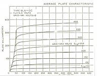
The 6C6 pentode as a driver.
There isn’t much data available covering the 6C6. With the exception of the inter electrode capacities all the 6J7 data can be used for design. The most comprehensive set of data I was able to find was published in 1945 by AWG (Amalgamated Wireless Valve of Australia), all attached here. Another good source is published in RDH4.
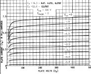
Referring to Post #12 the calcs shew plate current to be 0.7 mA, the screen current is 0.16 mA so the total cathode current would be 0.86 mA. And across the Rk of 2K that would be 1.47V. Reasonably close to the measured value of 1.7V.
OTOH in Posts #31 & 39, the screen voltage is measured at 86V while a plot of the 6J7 screen 470K loadline shews the screen voltage would be less than 50V. That is too large a difference to ignore. There appears to be an error.
Many experimenters don’t realize the pentode plate family of curves is very dependent on the screen voltage applied. That holds no matter whether the tube is a voltage or power amplifier. Unfortunately there is very little data of that kind published for pentode voltage amplifier tubes. But there is quite a bit covering power & beam tubes. A typical example on the 6L6GC can be found in some data sheets. The plate family of curves inflates to the line where grid one is a zero volts.
For voltage amplifier tubes the relation is close enough to linear to allow an estimate of the plate family when operated at a screen voltage other than what is published. If the screen voltage is halved the plate family of curves collapses’ to about ½ the current at normal voltage. Care must be taken, too steep a loadline will go thru the top of the plate family.
For sharp cutoff pentodes used as voltage amplifiers a method often used to decide on a screen resister value makes use of the ratio of plate to screen current at the same or similar voltage. For the 6C6/6J7 that is 4:1. The ratio of the plate to screen resistors then becomes 4:1. If the plate resistor is 75K as it is here the screen resistor would be 300K. Then use an Rk that sets the operating point somewhere on the plate voltage that will adequately drive the output tube. 🙂 👍
There isn’t much data available covering the 6C6. With the exception of the inter electrode capacities all the 6J7 data can be used for design. The most comprehensive set of data I was able to find was published in 1945 by AWG (Amalgamated Wireless Valve of Australia), all attached here. Another good source is published in RDH4.
Referring to Post #12 the calcs shew plate current to be 0.7 mA, the screen current is 0.16 mA so the total cathode current would be 0.86 mA. And across the Rk of 2K that would be 1.47V. Reasonably close to the measured value of 1.7V.
OTOH in Posts #31 & 39, the screen voltage is measured at 86V while a plot of the 6J7 screen 470K loadline shews the screen voltage would be less than 50V. That is too large a difference to ignore. There appears to be an error.
Many experimenters don’t realize the pentode plate family of curves is very dependent on the screen voltage applied. That holds no matter whether the tube is a voltage or power amplifier. Unfortunately there is very little data of that kind published for pentode voltage amplifier tubes. But there is quite a bit covering power & beam tubes. A typical example on the 6L6GC can be found in some data sheets. The plate family of curves inflates to the line where grid one is a zero volts.
For voltage amplifier tubes the relation is close enough to linear to allow an estimate of the plate family when operated at a screen voltage other than what is published. If the screen voltage is halved the plate family of curves collapses’ to about ½ the current at normal voltage. Care must be taken, too steep a loadline will go thru the top of the plate family.
For sharp cutoff pentodes used as voltage amplifiers a method often used to decide on a screen resister value makes use of the ratio of plate to screen current at the same or similar voltage. For the 6C6/6J7 that is 4:1. The ratio of the plate to screen resistors then becomes 4:1. If the plate resistor is 75K as it is here the screen resistor would be 300K. Then use an Rk that sets the operating point somewhere on the plate voltage that will adequately drive the output tube. 🙂 👍
Attachments

Got some examples to shew us?Now, where did I put my soldering iron and my calendar schedule?
What about a 6v6 driving the 2a3? I ask because I've got some old engraved coke bottle sylvania begging for some electricity.
It might be useful to a lot of folks if you'd expand this to include resistive voltage dividers for G2. RDH4 covers the topic, but isn't really as fluidly written as it could be. Also, if you're interested, you could touch on the topic of G1-G2 mu and the "inner triode" of a pentode.For sharp cutoff pentodes used as voltage amplifiers a method often used to decide on a screen resister value makes use of the ratio of plate to screen current at the same or similar voltage. For the 6C6/6J7 that is 4:1. The ratio of the plate to screen resistors then becomes 4:1. If the plate resistor is 75K as it is here the screen resistor would be 300K. Then use an Rk that sets the operating point somewhere on the plate voltage that will adequately drive the output tube. 🙂 👍
Much thanks, as always,
Chris
I made an error here, not sure why, the bias voltage should be 0.86 mA x 2K, that being 1.72V,Referring to Post #12 the calcs shew plate current to be 0.7 mA, the screen current is 0.16 mA so the total cathode current would be 0.86 mA. And across the Rk of 2K that would be 1.47V
There is also one slide missing, I'll stuff that in later. 😱
I've used battery grid bias on a couple of projects. Neither of them use an input transformer.As to whether or not input transformer is justified, the alternative is input capacitor. Pick your poison.
One has the battery + to ground and a single battery is used to bias both preamp tubes. The other has the battery in series with the incoming signal, with the battery + connected to the wiper of the pot and a 1M grid leak resistor and each channel has its own battery.
Perhaps I was misinformed but I was told that, with the positive grounded, I needed to use a cap on the input but that, with the battery in series, the cap was not necessary. Can anyone confirm this?
If this is correct, it would not be necessary to use either a cap or an input transformer when the battery is in series with the incoming signal.
Anyway, that's how I use them and I haven't noticed any issues. I have no idea how the outputs of the various sources are configured but none of them use balanced outputs.
I don't see any principle problem with such connection. But transformer input has several advantages. One is high impedance, but low DC resistance of the input circuit, which eliminates resistor' s thermal noise. It also makes low DCR path to grid for safe fixed bias operation. Transformer allows balanced-to-unbalanced transition at the input and allows configuring gain structure of an amplifier. Transformer isolates input, breaking ground loops. Additional cost of input transformer is therefore worth it in terms of amplifier performance, so I don't think that eliminating transformer as a design goal is justigied.Perhaps I was misinformed but I was told that, with the positive grounded, I needed to use a cap on the input but that, with the battery in series, the cap was not necessary. Can anyone confirm this?
If this is correct, it would not be necessary to use either a cap or an input transformer when the battery is in series with the incoming signal.
A typical CD player output has an op-amp whose out pin is connected via series 100-200 Ohm resistor and 100 uF electrolytic capacitor to RCA jack. The resistor serves to block oscillation. There is also muting transistor parallel to output - it grounds output when not playing. The op-amp has DC feedback loop to keep output pin DC offset at zero.Anyway, that's how I use them and I haven't noticed any issues. I have no idea how the outputs of the various sources are configured but none of them use balanced outputs.
Member
Joined 2009
Paid Member
I have read that: transformers are the most imperfect of all available passives, technically they are beat solid by capacitors.
That is a lot of hardware & expense ($$$) to accomplish very little, Basically just something to look at, 🙂 👎
I agree, a lot of money for an entry level amp.
cheers
pos
As to whether or not input transformer is justified, the alternative is input capacitor. Pick your poison.
Well, find an accurate capacitor and it will blow away the tranny with better low and high frequency response,
much less phase shift, lower distortion, less chance of resonance problems etc.
One has to also remember that all the dbs add, so -1db here and -1db there, another -1db at
X frequenciy) adds for -3db, with accompaning phase shift at X frequency. -1db and -0,4db
at X frequency gives -1.4db at X frequency. Phase shifts also "add".
By the way, I also saw a frequency response (FR) is -3db at 30khz, As such, the response will also be
down some at 7.5khz. Notice the dropping is well over octave ranges. That is not unimportant.
Normally that kind of drop will negatively affect the attack (rise time) of the music, harmnic structure
of the instrument/voice etc. Of course with higher orders of distortion from all the stages combining
might artificially give a snappier sound.
cheers
pos
Last edited:
Eliminating an input transformer was never a "design goal" as it was never under consideration.I don't see any principle problem with such connection. But transformer input has several advantages. One is high impedance, but low DC resistance of the input circuit, which eliminates resistor' s thermal noise. It also makes low DCR path to grid for safe fixed bias operation. Transformer allows balanced-to-unbalanced transition at the input and allows configuring gain structure of an amplifier. Transformer isolates input, breaking ground loops. Additional cost of input transformer is therefore worth it in terms of amplifier performance, so I don't think that eliminating transformer as a design goal is justigied.
A typical CD player output has an op-amp whose out pin is connected via series 100-200 Ohm resistor and 100 uF electrolytic capacitor to RCA jack. The resistor serves to block oscillation. There is also muting transistor parallel to output - it grounds output when not playing. The op-amp has DC feedback loop to keep output pin DC offset at zero.
I have a large collection of vintage tube amps, many of which are highly regarded, and not a single one of the them uses an input transformer. Well, I do have a few old PA amps that have the option of using plug in versions on their microphone inputs.
And I've seen many, many DIY designs posted here and on other forums and only a few seem to use input transformers. So I guess I've always considered them to be unnecessary. Iron, in general, is not cheap either.
I'm not particularly technical so I can't comment on some of the "advantages" you mention. As with many technical advantages, I don't doubt they exist and can be measured, but I wonder if they are audible in most situations. Many technical / engineering advantages seem to result in increased cost and complexity yet they don't have much to offer from a practical / audible standpoint.
For example, I'm not sure if I've ever heard thermal noise from a resistor except perhaps from a way out of spec carbon comp in a vintage amp that's in dire need of restoration. And, again I may be misinformed, but I always thought resistor noise was more of an issue when the resistor was dropping a lot of voltage and / or had a lot of current passing through it. Resistors on the input don't generally have either do they? Isn't that why, despite being shunned elsewhere, carbon comps are generally considered to be acceptable, or even preferable, when used as grid stoppers?
And your comment about how input transformers provide a better transition from balanced-to-unbalanced input. Some people may use sources with balanced outputs, but I suspect that the vast majority use common CD players, streamers and DACs with RCA outputs.
And input transformers may have high impedance. But I was always under the impression that most all modern sources have very low output impedance. So low that they have no issue matching up with even SS or Class D amps that have low input impedances. Wouldn't tube amps, which have much higher input impedances, make input transformers even more superfluous?
Anyway, my point was simply that your statement, "As to whether or not input transformer is justified, the alternative is input capacitor. Pick your poison" presents a false dichotomy.
Obviously, battery grid bias, can be used without either.
I have read that: transformers are the most imperfect of all available passives, technically they are beat solid by capacitors.
I have seen such, but I would be careful what you read and believe. I have sonically tested monoblock amplifiers,
in the lab, that were so close to perfect, it was nearly impossible to distinquish between the input signal
and output of the amp. Thus the OPT was doing quite well under load.
cheers
pos
- Home
- Amplifiers
- Tubes / Valves
- Developing a 2A3 SET