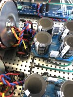
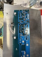
Had time this morning to install bridges on channel with my original wiring. Original wiring is right channel in pic…Left in pic is last suggested wiring.
Fired it up…no dice. The noise is still there…and it sounds worse for some reason.
I didn’t revert the wiring on the other channel…didn’t think it would matter if I wasn’t powering it up. Maybe the modified ground wiring is affecting this channel for the worse as well?
I think I did things correctly with the snubbers.
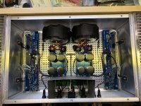
Added a few more pics of them installed in the case.
Ideas???
Fired it up…no dice. The noise is still there…and it sounds worse for some reason.
I didn’t revert the wiring on the other channel…didn’t think it would matter if I wasn’t powering it up. Maybe the modified ground wiring is affecting this channel for the worse as well?
I think I did things correctly with the snubbers.
Added a few more pics of them installed in the case.
Ideas???
Attachments
there must be something differentiating these two amps, one being buzz-free and second being buzzy
unfortunately, conclusion of what is that exactly, is possible only with more work ....... either changing blocks in it, or even migrating them from buzz-free amp
how you decided what value of resistor is in snubbers?
unfortunately, conclusion of what is that exactly, is possible only with more work ....... either changing blocks in it, or even migrating them from buzz-free amp
how you decided what value of resistor is in snubbers?
Got resistor value from Quadimodo thread after posting an inquiry with my transformer info.
rhthatcher replied with values he had used with same transformers successfully
I’m thinking the same…need to determine noise is not from amp boards in second amp
Not excited about idea of messing around with quiet amp to use for testing 😒
rhthatcher replied with values he had used with same transformers successfully
I’m thinking the same…need to determine noise is not from amp boards in second amp
Not excited about idea of messing around with quiet amp to use for testing 😒
considering that you made first one, and considering that you have same level of buzz in both channels, things are even more confusing
schmtc and parts are same in both amps, there is supposedly no difference between first and second
schmtc and parts are same in both amps, there is supposedly no difference between first and second
Sonidos are playing morning, noon and night.
They are continuing to make me smile more every day.
Only criticism I could come up with…in a dead silent room with no track playing you can hear the field coil power supply humming a little.
It is not as apparent if it is set to deliver lower current. This is my OCD at work and really doesn’t impact my listening experience.
Undoubtedly, this is the best sounding open baffle system I have put together so far.
Some adjustments to placement and toe in have just made them even better. Sound stage got bigger and deeper.
The tonal balance is surprisingly neutral with a wide variety of music.
I can easily play at “Honey Can You Turn That Down?!!!…I’m Working!” levels with the F2J driving them.
Had Rodrigo and Gabriella enthusiastically loud yesterday morning. Her percussive slams to the body of her guitar went right through my chest.
I wonder how much the baffle design change and placement has played a role in this.
I want to be able to retest some drivers I’ve used along with some new ones in exact duplicates of the baffles as an “Apples to Apples” comparison.
I suppose some sweeps using my mic and REW at some point would be useful.
When I’m not trying to sort out the J2 I’m usually sitting in front of the Sonidos…unless wifey catches me and puts me to work 😉
glad that you're happy with those
will take a look tonight on schm you sent me (Varga's PSU) and if I have something useful to say, will write here
most likely "just" level of filtering ...... though, ideal CS should suppress any ripple
meaning, actual CS isn't good enough
will take a look tonight on schm you sent me (Varga's PSU) and if I have something useful to say, will write here
most likely "just" level of filtering ...... though, ideal CS should suppress any ripple
meaning, actual CS isn't good enough
Finally stopped my sulking about having to take apart my #1 BJ2 that is quiet.
Initial test was pull the left channels from both (which have same unmolested original wiring scheme I did…#2 also has snubbers) and switch them.
Did test before hand to confirm things were as I left them regarding noise in #2 and #1 being completely quiet.
Well…noisy left amp channel from #2 swapped into #1 quiet
took noise with it.
Further test showed the right channel in #1 stayed quiet…so noise is somewhere in the #2 amp board.
Also tested right channel still in noisy #2 case by itself…still noisy.
Installed good quiet left channel #1 into #2 chassis with still noisy right channel.
Sound test showed left channel from #1 stayed dead quiet even in the #2 chassis. Right #2 channel remained noisy in same case.
I did a side by side visual inspection of both left channels and took some pictures…I see no difference other than leads to transistors are slightly longer on #2 channel.
The quiet #1 left channel was one of the raffle boards from BAF 2019.
It was actually a little more temperamental during build regarding mask lifting during soldering…#2 was a breeze to work with in comparison.
I only noticed difference in layout during build having to do with a few pads added for adjustment of components on second set of boards…but they are left empty and all values on both boards should be the same.
Re-checked orientation of components between both boards.
Checked value of resistors installed in sockets at Rx22, x23 and x18…same in both.
I checked orientation of transistors…they look correct.
I checked that I modified ground at input the same for single ended source.
Do I shorten transistor leads?…or do more thorough testing of resistor values mounted in both boards?…I did test them all (sometimes twice, thrice) before mounting.
Caps are same values in same locations…itty bitty 10uF 63V are different brands between boards.
Attachments
I went back into BJ2 amps today.
I reversed ground wiring changes in #2 case for right channel so it matched wiring again of the left channel which I did already test quiet #1 left amp board on and it remained quiet in #2 case.
My intention next was to swap the right channel amp boards of both cases and perform the same test to see if I got the same results of #1 quiet amp board staying quiet in #2 case and etc.
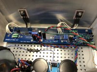
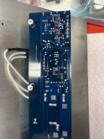
While I had the right channel boards out of the cases I labeled, compared and took pics of both.
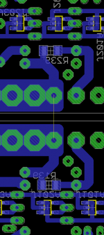
In the process I noticed a difference between the #1 and #2 right amp channel boards.
There is a spot for R139 on the #2 board that has a SMD resistor already mounted…not sure of value….I tried to measure it, but there appears to be no resistance due to the fact that I bridged the input (-) to ground as I am using single ended RCA source.
I assume R239 is also present on the #2 left amp channel board…but that I didn’t notice it. I would have to check.
There is no R139 on #1 right channel board…or maybe I’m blind?
My understanding was adding R139 helped amp offset “behave” better using Semisouth.
I’m using all IRFP right now.
Any chance this is causing the noise issue?
I reversed ground wiring changes in #2 case for right channel so it matched wiring again of the left channel which I did already test quiet #1 left amp board on and it remained quiet in #2 case.
My intention next was to swap the right channel amp boards of both cases and perform the same test to see if I got the same results of #1 quiet amp board staying quiet in #2 case and etc.
While I had the right channel boards out of the cases I labeled, compared and took pics of both.
In the process I noticed a difference between the #1 and #2 right amp channel boards.
There is a spot for R139 on the #2 board that has a SMD resistor already mounted…not sure of value….I tried to measure it, but there appears to be no resistance due to the fact that I bridged the input (-) to ground as I am using single ended RCA source.
I assume R239 is also present on the #2 left amp channel board…but that I didn’t notice it. I would have to check.
There is no R139 on #1 right channel board…or maybe I’m blind?
My understanding was adding R139 helped amp offset “behave” better using Semisouth.
I’m using all IRFP right now.
Any chance this is causing the noise issue?
Attachments
R139/239 are additional 1M resistor, only on latest gen of pcbs
role is to prevent neg input floating, just in case someone left both inputs free, it's having nothing with better offset - which is normal functional behavior
anyway , that can't be cause of your troubles
role is to prevent neg input floating, just in case someone left both inputs free, it's having nothing with better offset - which is normal functional behavior
anyway , that can't be cause of your troubles
Attachments
Sorry…I misinterpreted postsource resistors, SS down , IRFP up
compare posts #49 and #116
choose what you like more
to make DC ofset behavior more friendly, change R139/239 smd resistor value to 100K
or simply solder plain 0207 size 100K across the existing one - use surrounding pads
though, I'm not loosing sleep regarding that - simply grounding both inputs is my regular procedure while setting da beast
I’ll look over boards more carefully again…then proceed with testing to see if quiet #1 right channel remains so in #2 case
Finally stopped my sulking about having to take apart my #1 BJ2 that is quiet.
Initial test was pull the left channels from both (which have same unmolested original wiring scheme I did…#2 also has snubbers) and switch them.
Did test before hand to confirm things were as I left them regarding noise in #2 and #1 being completely quiet.
Well…noisy left amp channel from #2 swapped into #1 quiet
took noise with it.
Further test showed the right channel in #1 stayed quiet…so noise is somewhere in the #2 amp board.
Also tested right channel still in noisy #2 case by itself…still noisy.
Installed good quiet left channel #1 into #2 chassis with still noisy right channel.
Sound test showed left channel from #1 stayed dead quiet even in the #2 chassis. Right #2 channel remained noisy in same case.
I did a side by side visual inspection of both left channels and took some pictures…I see no difference other than leads to transistors are slightly longer on #2 channel.
The quiet #1 left channel was one of the raffle boards from BAF 2019.
It was actually a little more temperamental during build regarding mask lifting during soldering…#2 was a breeze to work with in comparison.
I only noticed difference in layout during build having to do with a few pads added for adjustment of components on second set of boards…but they are left empty and all values on both boards should be the same.
Re-checked orientation of components between both boards.
Checked value of resistors installed in sockets at Rx22, x23 and x18…same in both.
I checked orientation of transistors…they look correct.
I checked that I modified ground at input the same for single ended source.
Do I shorten transistor leads?…or do more thorough testing of resistor values mounted in both boards?…I did test them all (sometimes twice, thrice) before mounting.
Caps are same values in same locations…itty bitty 10uF 63V are different brands between boards.
well, I actually re-read your post and wasn't any smarter after that, so sorta left it to 'small brain' to chew on and reply later
can't say that I have any interesting idea what to do now...... thinkinthinkinthinkin.......
considering how many of these are made, and - excluding operator's errors, none had a problem in setting and functionality, I can't think of some inherent flaw, neither in pcb nor in pack of parts I've sent you
caps, in general, all being intended Panasonics, but even if different - all being made by major brand and always from reputable vendor
far from me being able to imagine all possible scenarios, and there lies the problem ......
now, few ideas . easy to implement
- 680-2n2 cap, soldered betwen B-E of T111/211; even if noise is not generated in that CCS, it can't harm
- you can do the same for M101/201, cap between G and D....... pre or post gate resistor
- if you solder temporary 10uF cap (plus up, neg down) across R122 and power it up, observing noise - it'll exclude FE (kill entire modulation from it) so it can say more from where noise is generated - FE or OS itself; sorta just a confirmation test, counting that noise is in FE, but we'll know more
Progress…
Well, first I did confirm that quiet #1 right channel amp did also stay quiet when installed into #2 case…it did.
Stared for a while at the #2 amp boards.
I could not get it out of my head that everything seemed right…except I had this feeling it had to be one if my bright ideas (read stupidity) that was causing the problem.
One thing that stuck out like a sore thumb was the longer wires I used to remotely connect the transistors to the boards.
I had given myself a little more length to make connections easier in #2 amp.
I also remembered I had used 100 Ohm gate resistors that were previously soldered to #1 board because I was running short…they tested good, but I now had doubts.
Well…I shortened wires to match #1 amp boards and installed new gate resistors on the #2 right channel amp board.
Installed it in #1 case and fired it up.
At first there was a very slight noise coming from test speaker. I shifted it closer to me…then it was as quiet as can be. Might have been loose wire at speaker terminal?
Hoping that’s that and same treatment to #2 left amp channel will cure my woes.

well, it seems constantly repeated sentence of "everything exactly the same as in amp #1" finally came to verification .....
there is a reason why some things are non-critical and forgivable in amplifiers having moderate OLG, thus increased level of NFB , versus amplifier as this one is - higher OLG. higher NFB, thus sensitive to sparrow's fart in next block
sometimes, when on verge, even 5mm of unnecessary wire length can ruin a day ( or week(s))
I know - easy to preach after the battle, but this battlefield wasn't exactly on my bench, so pardon moi
So…I was wrong…again…seems to be what I’m best at… 🤦♂️
I have some very strange behavior going on with this second set of BJ2 boards that I don’t understand.
I’ll try to describe it as best I can…sorry if this is long winded.
I retested several times yesterday…because of doubts I had regarding noise I heard when I first fired up the amp channel that I shortened the transistor leads and replaced the gate resistors on.
I have noise on start up still.
I observed during retest that when I picked up the speaker I was testing with that it seemed to have an affect on the noise coming from the speaker.
The speaker was sitting on a separate surface from my bench with about 3 meters of cheap 16 gauge two conductor speaker cable between it and the amp.
What I observed was that when I was holding the speaker up closer to my ear and the wire connecting it to the amp lifted off the concrete floor the noise nearly went away.
If I dropped the wire back down so it made contact with the concrete the noise came back.
I did this experiment with both of the noisy amp channel boards (with and without shortened transistor wiring and gate resistors) and got the same results.
At some point both the noisy channels got quieter and the phenomenon was less pronounced.
My first guess was I was creating some kind of ground loop by holding the metal speaker frame and standing on the same concrete that the speaker cables were making contact with (with rubber soled sneakers on🤷♂️)
Further testing today revealed a little more.
When I performed the same experiment with the test speaker connected to the case with the quiet amp boards I am NOT able to get any of this noise phenomenon to occur. No noise on start up. No noise holding the speaker regardless as to whether the cables touched the floor or not. It is so quiet I have to touch my ear with the speaker to hear that it is on.
I realized I needed to be more consistent
with further testing.
I retested all four amp channels again.
The amps were cold.
I made sure all had their inputs shorted.
I first coiled the speaker wire up with velcro so it didn’t make contact with the ground.
The speaker sat closer to the amp on the vinyl seat of a stool.
I made sure not to touch anything else when powering on the amps except the plastic power switch.
The first noisy channel I tested was the one I had just worked on.
It made noise on start up. It seemed like it wasn’t going to stop. After a minute or so I reached to shut the power off…and touched the chassis by accident. This seemed to reduce the noise.
Instead of shutting the amp down, I went on to uncoil the speaker wire and alternate it making contact with the floor while holding the speaker. Noise came and went.
At some point the noise subsided, but never got as quiet as the first set of amp boards.
This really made me scratch my head. I need to confirm that touching the chassis has an affect on the noise.
I repeated the same test on the other noisy amp channel…this time being careful not to touch the chassis.
I got noise on start up. Let it sit and listened. Eventually the noise subsided on its own…but not as quiet as the first set of amp boards.
I let the speaker cable drop to the floor and picked up the speaker. Noise came and went with the cable making and losing contact.
As I said…none of these tests had any affect on the case with the first set of amp boards.
At this point I am wondering if I have more than one issue.
Perhaps there is a grounding problem?
Is it possible that this second pair of amp boards might be producing excessive dc offset from a cold start up that is eventually subsiding as the circuit stabilizes?
When I originally fired up both pairs of amp boards in their cases I followed the same procedure regarding initially setting Iq and adjust dc offset and then allowing the amps to come up to temp equilibrium and adjusting them a few more times. I followed up by repeating the process the next dayfor both amps before I finally tested them with speakers.
Hi ZM
I haven’t tried anything from post #855 yet.
Wifey did have oral surgery and I have been looking after her.
I was thinking (hoping) the rewire and gate resistor change had been the solution.
Then when I noticed this weird behavior. I was confused and became preoccupied with trying to figure out what was really going on with the noise symptoms
I felt like I didn’t have a clear picture because all I had ever done previously was fire the amp up, heard the noise and shut it down.
Please excuse my polluting the thread. I’m groping in the dark here.
In your suggestion #1…680-2n2 is equal to .68-2.2 nF as I understand it?
Not having luck finding anything in this value range in my stores. The smallest I found was some .047 uF in poly, mylar or ceramic.
I did find some 10uF 35V elctrolytic Silmic ii.
R122/222 are socketed…so fairly easy to pull them…add the cap across legs… and plug back in.
I don’t know what proper “up/down” polarity is in the cicuit.
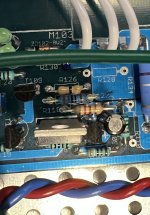
I attached a pic of R122 and surrounding components…can you edit with “+” on appropriate leg of R122 resistor?
I haven’t tried anything from post #855 yet.
Wifey did have oral surgery and I have been looking after her.
I was thinking (hoping) the rewire and gate resistor change had been the solution.
Then when I noticed this weird behavior. I was confused and became preoccupied with trying to figure out what was really going on with the noise symptoms
I felt like I didn’t have a clear picture because all I had ever done previously was fire the amp up, heard the noise and shut it down.
Please excuse my polluting the thread. I’m groping in the dark here.
In your suggestion #1…680-2n2 is equal to .68-2.2 nF as I understand it?
Not having luck finding anything in this value range in my stores. The smallest I found was some .047 uF in poly, mylar or ceramic.
I did find some 10uF 35V elctrolytic Silmic ii.
R122/222 are socketed…so fairly easy to pull them…add the cap across legs… and plug back in.
I don’t know what proper “up/down” polarity is in the cicuit.
I attached a pic of R122 and surrounding components…can you edit with “+” on appropriate leg of R122 resistor?
Attachments
- Home
- Amplifiers
- Pass Labs
- Babelfish ᄅſ....or FW J2 on Steroids .... or Not your Father's J2!