Thanks! With the exception of the Austin boards for the M2x, it's the tightest through-hole build that I think I remember building. I just have to take my time. Plus, even though I use "No-Clean" flux / solder, I like shiny boards. 😀
Edited to add - the Iron Pre has a few sections with fairly high parts density too. 😀
Edited to add - the Iron Pre has a few sections with fairly high parts density too. 😀
😕
Hi ZM and Group -
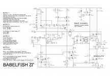
I have studied the schematic. I am perplexed. Per normal process, I always short the input when biasing or nulling offset. For RCA's (In to GND) for XLR (In- and In+ to GND).
For this amp it seems ultra-critical. I forgot to short the inputs initially, and the bias was moving oddly or not at all. Without the inputs shorted, I get an exceptionally low bias reading. Short inputs, and it automatically pops correct. Either I am missing something in the circuit for understanding and/or I have built something improperly.
Any light you can shed is greatly appreciated. I checked back in the threads, and have not seen anything or I missed it.
BTW - super simple to get to 800mV across the 1R0 (X33 and X36) resistor set and very stable on both bias and offset. I have not tried to go to 900mV yet. Want to check that my bias process is correct and let it cook and move up gradually.
Just wondering about why shorting the inputs has such an impact on the bias.
Edited to add -
Well rats. I went to bias up the other channel, and none of the LEDs are lit. I checked solder joints etc. Admittedly... 😱 ... I had installed them backwards on this channel and had to desolder and put them back. DOH! I quite easily could have damaged one or more. Is there a specific green LED that is best for this circuit? If so, which ones should I order. I probably have 100's of just plain generic ones, but I want to be certain before replacing (again).
I have a bunch of these as an example...
https://www.mouser.com/ProductDetai...GAEpiMZZMt82OzCyDsLFLvoqsggc1EKP%2Bwq8dfohko=
Hi ZM and Group -
I have studied the schematic. I am perplexed. Per normal process, I always short the input when biasing or nulling offset. For RCA's (In to GND) for XLR (In- and In+ to GND).
For this amp it seems ultra-critical. I forgot to short the inputs initially, and the bias was moving oddly or not at all. Without the inputs shorted, I get an exceptionally low bias reading. Short inputs, and it automatically pops correct. Either I am missing something in the circuit for understanding and/or I have built something improperly.
Any light you can shed is greatly appreciated. I checked back in the threads, and have not seen anything or I missed it.
BTW - super simple to get to 800mV across the 1R0 (X33 and X36) resistor set and very stable on both bias and offset. I have not tried to go to 900mV yet. Want to check that my bias process is correct and let it cook and move up gradually.
Just wondering about why shorting the inputs has such an impact on the bias.
Edited to add -
Well rats. I went to bias up the other channel, and none of the LEDs are lit. I checked solder joints etc. Admittedly... 😱 ... I had installed them backwards on this channel and had to desolder and put them back. DOH! I quite easily could have damaged one or more. Is there a specific green LED that is best for this circuit? If so, which ones should I order. I probably have 100's of just plain generic ones, but I want to be certain before replacing (again).
I have a bunch of these as an example...
https://www.mouser.com/ProductDetai...GAEpiMZZMt82OzCyDsLFLvoqsggc1EKP%2Bwq8dfohko=
Last edited:
Scratch that for the LEDs. Had the odd-duckling LED on right board installed backwards. DoDo me. I'll turn it around tomorrow. Sheesh. LOL! 😀
I don't recall needing to short the input to correctly bias, though I also wired for SE only. Hmm. Wonder if there's a grounding issue somewhere?
Thanks guys! Glad to know bajjisw that I was not the only one.
I'm pretty sure I've got at least one bad LED on the right board. At least that seems like the most logical situation since I flipped them all and then one of them twice. 😀
Silly question, but can I just put 3V or so across each one to check them individually before yanking them all out and replacing. Zeners are all the correct way around etc.
Anything else seem like it would be logical to check before I check the LEDs?
Hey IAIMH. If you haven’t already, revisit posts #116 and #252. #116 to make sure you have the right combo of source resistors for Semisouth down. And #252 for setting instructions. That should confirm the need to short inputs. For green LEDs ZM recommends a green led with forward voltage of 1.9v, I believe. Correct me if I’m wrong Mighty ZM. I’ve been using these for all of my ZM builds. LTL-4231NLC
Thanks! I have a schematic that does not have those resistors swapped. I clearly overlooked that post and/or a new version of the schematic. I've been using the attached.
ZM - Can you please confirm if I should be using the schematic in #116 or the attached that you sent me in the zip file. I can swap two resistors with no worries. Note for your ease - difference is R132 and R133.
Rats, the LEDs I have are 2.1V forward voltage.
re: 252 - He wrote that one to me, so I had that in my notes. At least I did one thing correctly. 😀
Attachments
Last edited:
LEDs are not critical at all, nor is critical difference of few hundreds of millivolt
regarding Source resistors for different combinations of parts in output (IRFP , SS) , just track linearly posts in thread ....... I simply posted things as they were tested
I'll go back now in thread and see and inform here
regarding inputs grounding while setting - it simply helps in setting procedure to be faster
once when things are in ballpark, it is not so critical anymore
For those keeping score at home, I confirmed that I had killed the poor odd-duck LED on the right board.
ZM - LEDs within a batch or bag seem to have varying forward voltages. I have a few of my 2V1 forward voltage LEDs that measure down in the 2V0 range.
Any harm in swapping in one of those for the single dodo LED, or should a be a patient person and order an identical? From how I interpret the circuit and how the CCS works with the LEDs and 4148 off the gate (again... limited knowledge) it should be just fine and not a problem at all, but I want to be doubly sure.
Thanks everyone! This is the last amp that I want to ook up. Already embarrassed that I ooked the LEDs. That's what I get for stuffing while tired.
LOL!!!!! MZM is the master. Edited to add that he answered me above. 😀 😀
source resistors, SS down , IRFP up
compare posts #49 and #116
choose what you like more
to make DC ofset behavior more friendly, change R139/239 smd resistor value to 100K
or simply solder plain 0207 size 100K across the existing one - use surrounding pads
though, I'm not loosing sleep regarding that - simply grounding both inputs is my regular procedure while setting da beast
Hi ZM -
Thank you. I am using the one in #49. I was not smart enough like CodyT to install the pegs to allow me to swap them out easily, so I will leave it.
It looks like the swap in resistors results in a teeny bit less 3rd and 4th. I might save that to another time after listening for some time. It could be a fun comparison some time in the future.
re: biasing and offset. It's a breeze. Not a worry in the world re: how easy it is to dial in on the one channel I had up last night. I just forgot to short the inputs, and it was wonky. So, I pulled out the schematic to try and understand. No need for me to change it.
Thanks as always. May have tunes later on test speakers. Swapped out the LED, and I am back in business.
leds can be tricky fragile thingies
treat them properly ( orientation and clean fast soldering) - no worries
meddle with them too much - they're Dodo
earlier - when I didn't had solder sucking gun station, whenever I desolder one from pcb (those having short legs) - I simply tossed it in trash bin and used new one
better safe than sorry
Both channels cooking. Set to ~850mV across X33 (both X32 and X35 are 0R6. X33 and X36 are 1R0). Offset and bias hold rock steady to within a mV. Just taking my time and easing it up before hooking up test speakers. I'll set the target for 900mV => 1A8.
As always, thanks to everyone. I still get nervous every time I take the Variac out, move an amp off the bench and hook it to mains for final tweaks / bias with real house voltage etc.
Edited for clarity on resistor values and placement since there are a few schematics.
As always, thanks to everyone. I still get nervous every time I take the Variac out, move an amp off the bench and hook it to mains for final tweaks / bias with real house voltage etc.
Edited for clarity on resistor values and placement since there are a few schematics.
Last edited:
Grinning from ear to ear. No critical listening yet, and I see a few tweaks in the future to get it "perfect" or just to have me sleep better.
I could only get the bias on one side up to 1A7xx (854mV). Plenty of turns left in the pot, it just would not go any higher. I don't know if adjusting R123 is the solution, since the pot still had "room". The other side would easily get up to 900mV without issue. Is that due to the relative balance between the IRFP150s and the SS devices?
Balanced both channels at 854mV with offset below 1mV when all hot and bothered and stable. Only wanders a bit during initial warm up.
I'll leave it on the test speakers for a few hours and then hook it up to the system.
😀 😀 😀 😀 😀
Edited to fix typo.
Last edited:
....
Balanced both channels at 854mV with offset below 1mV when all hot and bothered and stable. Only wanders a bit during initial warm up........
call it good
1A8 isn't carved in stone
- Home
- Amplifiers
- Pass Labs
- Babelfish ᄅſ....or FW J2 on Steroids .... or Not your Father's J2!