now - I already explained that to your fuzzy Mentor Chakija - solder resistor between -IN and GND pads , value whatever you have in drawer - 100K to 1M, lower the better
that will cure problem with open inputs; though, never was my big concern, simply because of habit to ground inputs while setting and later inputs are always "terminated" in proper way
now , when inputs are grounded, clarify/confirm:
- you can bias it to intended Iq
- there is positive 1V4 DC offset at output?
..mentor is in Greece atm 🙂
Ok, 110k resitor added between - and gnd input.
I can lower the offset to 0 with input like this.
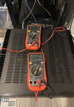
Max voltage across R133/R136 that I can get now is 20mV. If I open the input, I can bias it to 900mV.
Ok, 110k resitor added between - and gnd input.
I can lower the offset to 0 with input like this.
Max voltage across R133/R136 that I can get now is 20mV. If I open the input, I can bias it to 900mV.
gnd both inputs
ignore offset for now - can you bias it to intended Iq (even if setting dc offset for worse is needed for that) and, if yes, how much is that?
ignore offset for now - can you bias it to intended Iq (even if setting dc offset for worse is needed for that) and, if yes, how much is that?
Oki.. with both inputs having 110k to gnd.
Pots are both at the end of their travel. Bias voltage across R133/R136 is 25mV (while offset is -1.3V).
I can't get it to more then 25mV..
Pots are both at the end of their travel. Bias voltage across R133/R136 is 25mV (while offset is -1.3V).
I can't get it to more then 25mV..
when I said "gnd both inputs" that means - short both inputs to GND, tie all XLR pins together, or whichever way you can do this
once when you're in ballpark with settings, funny behavior with inputs would stop
if offset is negative, that means lower mosfet is open more than upper one
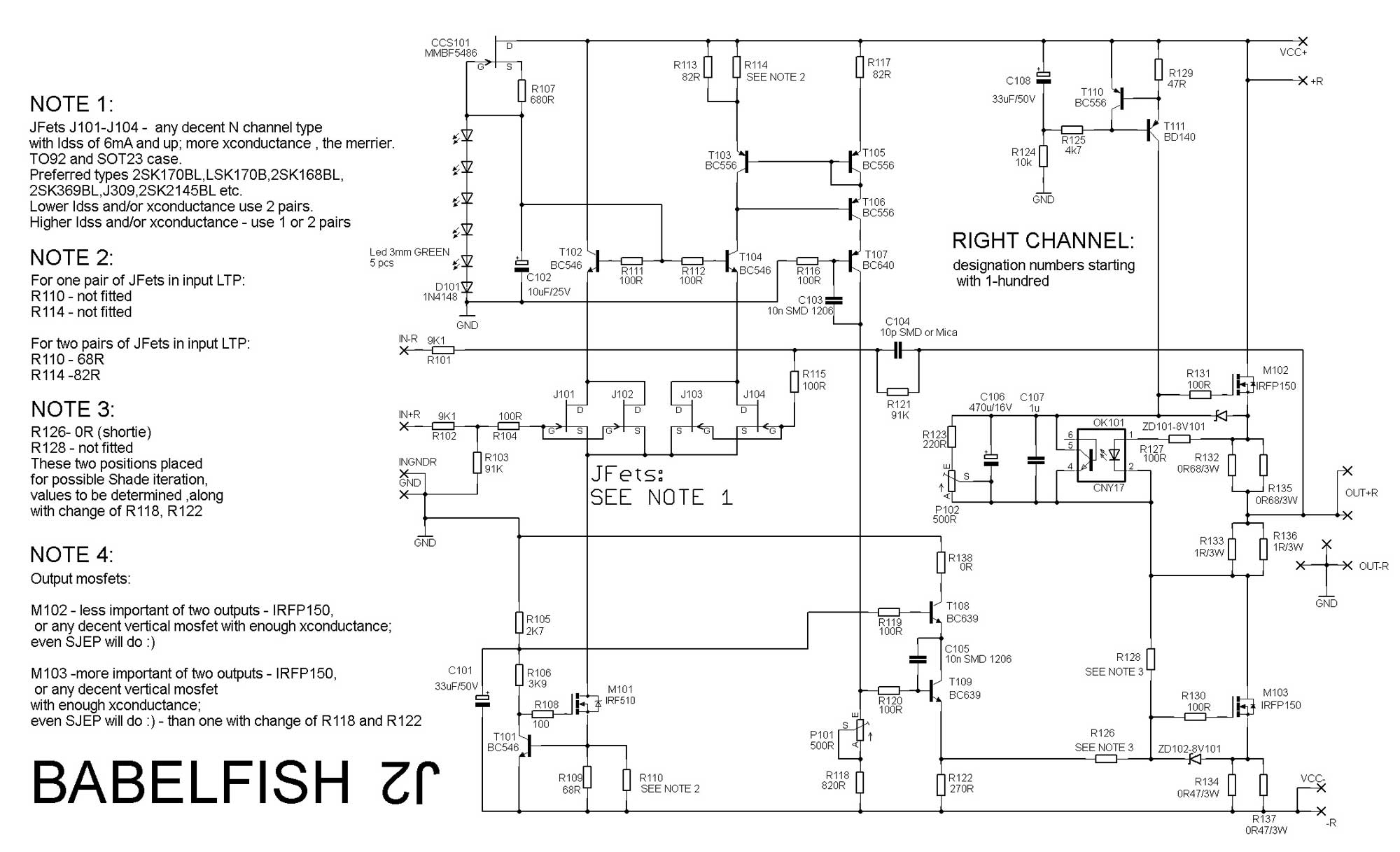
ref to sch in post #1, also attached here, set P102 to zero, replace R123 with 510R or 620R or 680, and try again
once when you're in ballpark with settings, funny behavior with inputs would stop
if offset is negative, that means lower mosfet is open more than upper one
ref to sch in post #1, also attached here, set P102 to zero, replace R123 with 510R or 620R or 680, and try again
Last edited:
yeah.. will do tomorrow as it's better to put socket pins for R123.
As this exercise will be needed again for sjep's..
As this exercise will be needed again for sjep's..

Zen, with inputs grounded and R123 680R, I can get desired bias.
Offset is positive 1.4v. To increase R118 to 1K from 820R? R122 is still 270R.
Offset is positive 1.4v. To increase R118 to 1K from 820R? R122 is still 270R.
Zen, do you remember what did you fix on Chaki pcb's? It looks like I have the same issue on both channels with hum in speakers and dc offset drifts when I touch heatsinks (even worse is that this tunnel have all four corners totally isolated from anything).
dunno
Chakija made a proper mess with his build, me ending changing almost all semis in the end and there was no problem when he did put them back in case
chassis properly on safety GND?
audio GND properly connected through 10R NTC (each channel separately) to chassis?
both inputs either grounded or signal cable from preamp connected (if SE, neg leg must be grounded)?
and - I strongly advise electrically and mechanically connecting that heatsink to rest of case; Gremlins never sleeps and you really don't know how stray capacitances are going to mess with your calm sleep
PCB's should be ok. I double checked everything before soldering anything. Additionally cleaned that near short on one channel mosfet pads..
You know that I usually check every component before soldering, but this time BC's where just throwed in. Outputs are original IOR ones.
Yes, chasis is on power GND. Audio GND's are also each on 10R NTC and then to the same GND point to chassis (same bolt ties all ground wires).
XRL interconnects are ok and also is the DAC.
Will ground heatsinks, trimm everything again and try it like that...
No luck.. With heatsinks grounded now it's hiss in speakers.
If input is grounded it's pure hiss, If XRL input is open (110K is in place between -in and gnd) it catch radio signal and change station with me around it 😀
I guess it's time to order semis from non local suppliers in Serbia..
If input is grounded it's pure hiss, If XRL input is open (110K is in place between -in and gnd) it catch radio signal and change station with me around it 😀
I guess it's time to order semis from non local suppliers in Serbia..
it depends - where you got them - I'm getting (almost) all my parts through local Vendors, but those are the guys with whom I'm working for past 20yrs or so, and their distribution chain is traceable all the way to manufacturer
if behavior is the same in both channels - there is some systematic ookup made on both sides
there must be ( I believe) somewhere back in the thread - schematic with some important voltage readings; if you can find it and compare with your situation
if behavior is the same in both channels - there is some systematic ookup made on both sides
there must be ( I believe) somewhere back in the thread - schematic with some important voltage readings; if you can find it and compare with your situation
It works stable now. Changed all the semis to nos Philips ones..
Will cook it for a few days and change to sjep's..
Will cook it for a few days and change to sjep's..
Naah.. pure coincidence. 🙂
Just managed to steal some time to solder between job meetings..
But we are having discussions about build of a xa252 😀
Just managed to steal some time to solder between job meetings..
But we are having discussions about build of a xa252 😀
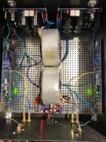
Babel J2 is happy in its new home. Dissipate 5U Deluxe. PSU’s are SLB. One per channel, fed by Antek 4222, 400va 22v secondaries. Getting +/-26.9v per board on the supply, under load. Playing some vinyl right now. Gillian Welch - The Harrow & The Harvest and Herbie Hancock - Fat Albert Rotunda. Phenomenal. Thanks again ZM. 🙂
Attachments
- Home
- Amplifiers
- Pass Labs
- Babelfish ᄅſ....or FW J2 on Steroids .... or Not your Father's J2!