Somehow i did think that the ADC input's was differental aka' could be used balanced, just a mistake.
The ADC input part of the CODEC chip is differential.
It is the ADC buffer circuit that takes a single-ended signal and does a converstion to differential. The reason here being that the MIDAS preamp itself does a Bal to SE conversion before the signal hits the ADC buffer.
Understandable that it all can be a little confusing but if you follow the schematics as posted you can see where these conversions happen.
Somehow i did think that the ADC input's was differental aka' could be used balanced, just a mistake.
Now if you really want to keep it all differential, our good friend @MagicBus already provided not only the info on how to do an initial mod for an additional switchable input exactly for that, but also shared a differential preamp of his own design quite recently. Combine the two and you have an on-demand switchable custom differential preamp that replaces the internal MIDAS preamp.
Of course, it's more work. I really wanted a super simple set of mods to get rid of most of the issues and I don't mind Single-Ended for analysis currently.
Morning here. (Another time at your'e place YashN 🙂 )
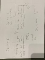
Well, i asked YashN howto mod the other channel, as i thought at that time i could make it aka' balanced.
Looking more carefully i see how it's working now.
The attached picture is what i send to YashN, asking him if it was right; but before he answered i allready did the unusefull 2. mod.
Please care, my schematic is only usefull for the working mod...
'YeashN answered afterwards, that if i would mod the other channel i got the wrong parts on my schematic.
Not sure the importance of this info+ Duo to some laungauge barrier for me, i wasen't aware this was what YashN meant i should post, for other not doing the same mistake. As YashN is very helpfull i ofcause will do, hope i got it right this time ?
Jesper.
Attachments
Another thing...
Reference to post #197 and #203 where @MaigcBus present's a card giving balanced input's and as qouted ::
"a new input, high impedance, true differential floating with attenuator and overvoltage protection, ready to accept an amplifier"
I might be in trying this, but have to ask first if this it right :
Will using diff. input from an "normal" SE output amp. give better noise figures and at same time reject some of the 50Hz + harmonics hum etc...
E.g. RCA +out ---> + IN & RCA gnd ---> - IN on the @MagicBus board.
I tried my non modded INPUT A (X8) with XLR inputs (pin 2 & 3 from RCA). It's actually looking a bit better noisewise, but not as good THD number's as with YashN mod that is...
Jesper.
Balanced inputs suppress common ground noise which often is an issue when measuring low THD+N levels. Furthermore balanced input is mandatory when testing BTL-outputs of TI-class-D, while a single ended measurement gives one order of magnitude worse THD+N.
Exactly! Or to put it simply, a balanced input works better for whatever kind of source.
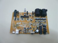
PS. I have been very careful not to introduce myself as an expert and this is generally my approach by choice... This thread is all about relentless experimentation and reading not least! Which is what I strongly encourage everyone to do! If I had to regret for every -catastrophic most of the times- mistake I've done, then you would get bored reading my apologies... 🙂 I'm posting some of my victims for your amusement. I'm still in doubt if I should have chosen "Laboratory Mouse" for forum nickname. Enjoy DIY!
PS. I have been very careful not to introduce myself as an expert and this is generally my approach by choice... This thread is all about relentless experimentation and reading not least! Which is what I strongly encourage everyone to do! If I had to regret for every -catastrophic most of the times- mistake I've done, then you would get bored reading my apologies... 🙂 I'm posting some of my victims for your amusement. I'm still in doubt if I should have chosen "Laboratory Mouse" for forum nickname. Enjoy DIY!
Attachments

For the Left Channel, doing the simple mod as I did for the Right Channel, here is what I exchanged in DM:
BTW, I made a mistake in my previous post regarding mathching. Only realised this morning on waking up:
Actually, you don't need to match the channels closely using the special modes (ARTA, maybe REW). That's the beauty of these algorithms.
In fact, I did a 4-channel version of that kind of calculation and showed some graph on 4 simulated channels in a thread about building a Phase Noise Analyzer somewhere on this forum, but I don't think anyone followed up.
You can re-use the same PSU-caps for new diode connection joints, and of course, transpose everything to the Left Channel.
The caps/vias for the Left Channel are: C85 and C34 though.
BTW, I made a mistake in my previous post regarding mathching. Only realised this morning on waking up:
Actually, you don't need to match the channels closely using the special modes (ARTA, maybe REW). That's the beauty of these algorithms.
In fact, I did a 4-channel version of that kind of calculation and showed some graph on 4 simulated channels in a thread about building a Phase Noise Analyzer somewhere on this forum, but I don't think anyone followed up.
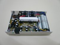
We can't make omelettes without breaking eggs.I'm posting some of my victims for your amusement.
I have a growing collection of some of the broken eggs in my stash. Fortunately, not many.
At least for electronic components, I mostly experiment with salvaged parts, and any mistake made on those don't hurt. For Tubes recently, I have done many experiments with low voltages, and learned a lot along the way. I even thought I had damaged the MOSFET I was using in an hybrid configuration at one point, but no... nothing ever broken here.
On the other hand, a recent excursion into resoldering on my SS amp just damaged one channel completely. That's a bigger loss as it was used for surround on movies, but still a small monetary loss (second-hand purchase). Another one was SMD desoldering and soldering when my adjustable iron was down, so I used a normal one... Cue in other small SMD parts than the single target flying all over from too much heat...
Will using diff. input from an "normal" SE output amp. give better noise figures and at same time reject some of the 50Hz + harmonics hum etc...
E.g. RCA +out ---> + IN & RCA gnd ---> - IN on the @MagicBus board.
If you try it on the other non-modded channel, you're well poised to make some comparative measurements and post the graphs. You may be surprised (and some others too).

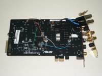
Evening here fellow diy'ers 😊
I'am preparing my Behringer for the mod & @MaigcBus's balanced input board.
I can't seem to quite understand what you write in post #203 @MagicBus.
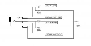
The direct in mod i did some time ago, i attached the 47uF capacitor at the extra-TRS plug, so that the signal from the preamp could enter the path via the capacitor when none jack was inserted into the extra-TRS plug.
Well i have no use i think of the preamp left channel, but maybe i got it wrong ?
Btw: The boards was verified fine at pcb-house after you did the correction, thank's a lot!
Jesper.
I'am preparing my Behringer for the mod & @MaigcBus's balanced input board.
I can't seem to quite understand what you write in post #203 @MagicBus.
I did take out my C34 left ADC BUFFER input-capacitor. But the signal comming from the preamp left is going into the + side of the C34 capacitor (i did confirm this with my scope) so the signal from the left preamp cannot enter the ADC BUFFER this way ?For the left channel, remove C34 and take a wire from the negative pad, no return to positive. The on board buffer for the left channel will be permanently stay disconnected. But wiring a TRS like in the schematic allows full functionality for the front panel input and controls just like the previous mode. The new buffer has just a bit higher gain at ~1,25.
The direct in mod i did some time ago, i attached the 47uF capacitor at the extra-TRS plug, so that the signal from the preamp could enter the path via the capacitor when none jack was inserted into the extra-TRS plug.
Well i have no use i think of the preamp left channel, but maybe i got it wrong ?
Btw: The boards was verified fine at pcb-house after you did the correction, thank's a lot!
Jesper.
Attachments

You are correct once again! I tried to figure out from old pictures as you already know the status of my poor HD202. For some reason they have made square the negative pad of the capacitor... So it is a wire from positive lead to the new pcb. The TRS wired as previously but the coupling capacitor for this doesn't have to be that big since the new input impedance is significantly higher.
@MagicBus... you do a h... of a good job, thank's!You are correct once again! I tried to figure out from old pictures as you already know the status of my poor HD202. For some reason they have made square the negative pad of the capacitor... So it is a wire from positive lead to the new pcb. The TRS wired as previously but the coupling capacitor for this doesn't have to be that big since the new input impedance is significantly higher.
Is the attached schematic correct then?
Got 3 quistions more 🙂
* Do i need a capacitor for the input to TRS jack from (C34+) ?
* Do i need the 100K resistor to GND ?
* Should i connect the extra/backplate TRS jack (S / GND) to Behringer GND also ?
Jesper.
Attachments
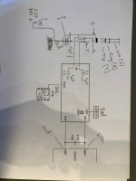
Schematic seems correct! You won't need a substitute for C34 neither 100k to ground. C1-C2 and VR1 on the new pcb take care of that. About grounding TRS sleeve, the new buffer input doesn't need any reference to ground. Maybe it could help with the on board preamp but most likely it should not make any difference. I would try it without ground for starters.
Cool... i got it thank's...Schematic seems correct! You won't need a substitute for C34 neither 100k to ground. C1-C2 and VR1 on the new pcb take care of that. About grounding TRS sleeve, the new buffer input doesn't need any reference to ground. Maybe it could help with the on board preamp but most likely it should not make any difference. I would try it without ground for starters.
When i got it all set up and working i will post some pictures,
Hopefully the parts and the pcb(s) will drop in next week.
Btw. : If i could kindly ask here if someone got one spare lt3045 & lt3094
The (especially) lt3094 seems hard to source right now.
I have some LM7809 & LM7909 for a start through!
Jesper.
For me, all components have become quite expensive to order. I usually order from Digi-key locally in Canada and pay something like CAD 8 for shipping when it's a small order. Combining orders to above CAD 100 gets us free shipping. Imagine my surprise when my last order came from the US instead of Canada, and I had to pay around a quarter of the total in import duties. Not too happy.
I believe I did have an LT3045 or something like that in there. Prices were already up, but with duties, even more so!
If you have some LM317s, they can be better than the old 7808s and 09s. Additionally, @Elvee has some simple add-on circuits to improve on the LM317 in a thread here.
I believe I did have an LT3045 or something like that in there. Prices were already up, but with duties, even more so!
If you have some LM317s, they can be better than the old 7808s and 09s. Additionally, @Elvee has some simple add-on circuits to improve on the LM317 in a thread here.
YashN...
It's getting more expensive those parts, but i live in DK and Mouser have a quarter in our neigbour country Sweeden.
Good thing is that eventhrough parts are comming from the US, all tax and everything is taking care of when i pay online. -Parts are not more expensive than local parts here in DK this way. So Mouser and partly DigiKey is my freind's 🙂
I know about the 317's but i have both 7809 & 7909 on my own stash, so they will be in for a start.
The 3045 & 3094 are backordred but orderable for expected within 2 months - So when everything is working (hopefully) i will proberly design a lt3045 +9vdc and a lt3094 -9vdc TO220 aka' pcb (this could be a nice sommer project)
If i got to much noise or some other issue, i will power it with 2 9vdc batteries.
I'am really looking forward to test this Magic balanced board, and most are ready on my Behringer now.
Jesper.
Hey here.
606-CM120MB
@MagicBus I ordred some of the lamps you described to use instead of R1 & R2 (33K / 3W)
I know that some instrument's are using lamps for measurements operation, or to have some input to behave better than resistors.
But i don't understand how excatly it's working, except that a lamp is aka' sort of resistor (variable that is).
Does the attached schematic where i "put" in the lamps instead of R1, R2 look right?
Anyone explain please how this work 🙂
Jesper.
Attachments
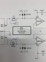
Current limiting resistors will dissipate excessive power to protect the diodes which in turn protect the opamp from high voltage. But adding in series resistors will add noise. Since this scheme is only needed when high voltage appears at the input, the idea with the lamps is to keep the resistance low when everything is within limits. The lamps' filaments read a few hundreds ohm when cool but will increase rapidly when have to dissipate power. That said, I've tested them for the first time in Pete Millett's PC interface after his suggestion and it was worst than plain resistors. They picked EMI or something and that interface doesn't have true balanced input to allow CMRR to work. But in my diy soundcard I was happy to see it works fine. So, if you are in for some experimentation, you could start from jumper wires -just remember there is no protection in this case- and compare with resistors and lamps. There should be sufficient CMRR in this circuit perhaps to go with the resistors. My soundcard is a complex assembly to try all this now.
- Home
- Design & Build
- Equipment & Tools
- Behringer UMC 202HD for measurements