Hey...
I also noticed that output of filtered CH-B (Right) is slightly worse when measuring.
But i prefer a clean sine-wave.
When using output CH-A (Left non filtered) the sine is flickering and noisy on my scope. (also shown in my previous post)
But you are right!
I will try to do a series of measurements later, going from -4.65dB to ~-20dB or so.
ALSO more interresting to see when i do "real world" measurement's that is!
- Maybe i get better result with a clean sine wave here... let's see when i get to it later.
Attached a couple of 44.1kHZ measurements 😎
Jesper,
Attachments
I think your plots are what we can expect. THD+N is dominated by harmonic distortion of the sound card, not by statistic noise. Thus you can improve the numbers by adding anti-phase harmonics to the generator signal. An option of REW I only heard about, but never used myself as the main THD+N contributor of my EMU sound cards has been noise.
This is my conclusion too. Why not keep the view to higher frequencies even if it's not so clear? That said, I do note Alfred's work for audio playback applications.Probing the output of my EMU sound cards with a scope showed ugly high frequency noise as well. So I did some tests with low-pass filtering to smooth the sine waves which apparently worked. But the measured numbers of THD+N in the audio band did not change at all. What we see on the scope is outband noise, not nice on the scope - but beyond audio relevance. The same applies to class d-amps. The rf-residual after filter gives a smeared sine-wave which contributes to noise far above the audio band. We do not "see" music on a scope with a bandwidth of 100MHz or more, the bandwidth limited soundcard measurements are a far better representation of what we hear. For my lab applications only I have built a latFET class-B-amp.
Btw, a 21kHz filter is no bad option at all but must be bypassed if you want to extend measurements beyond 20kHz with higher sample rates.
Hi all,
for pure music application I would agree. You will most likely not hear a difference.
For audio measurement, and that is what we taking about here, might be different.
I am aware of two effects which can hurt your measurement.
1) If you feed a slow amplifier with high frequency it might get nonlinear and starts mixing and creates signals or noise in the audio band you will not get rid off. To test for it you do a two sine waveform with two high frequency signals, but close in frequency, eg 19 and 20 KHz, or 39 and 40 or 79 and 80.
The effect is called IMD (Inter Modulation Distortion) With a good amplifier you will just see just these two frequencies at the output.
A bad one will create 18 and 21 KHz (or 38 and 41 or 78 and 81) which is called IMD3. ((2 x F1 -F2) and 2 x F2 -F1). Will not hurt if it is out of band.
But it also creates IMD2 which is just the difference of the two frequencies, 1 KHz in these examples, and this is in the audio band. No way to get it out.
2) If you feed an ADC with frequencies higher than Fsample/2 (Nyquist) it will fold it down in the audio band. Most ADCs use higher sample rates and digital filtering. But you never know.
If you do not see any of these effects you are lucky. But you are not on the safe side.
Alfred
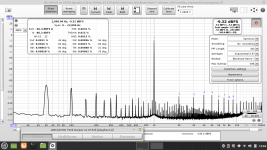
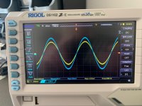
So this is best what i can get right now.
- To bad the forrest of 50Hz, 100Hz + freinds i got, but measurement's are much better than back when i started this journey (thank's MagicBus!)
Input CH-B (YashN modded) ---> Output CH-B (sine 1Khz / with 21kHZ 4. order filter)
On scope ::
Yellow = input to Behringer through voltage divider (1x probe)
Blue = output before voltage divider (10x probe)
Jesper.
Attachments
I'm a bit confused regarding the ultrasonic noise of CS4272 as it appears in this soundcard... According to datasheet, the DAC is oversampling -digital filter- with a stop band attenuation more than sufficient. It's all in the last pages. 90dB at Nyquist frequency for 48kHz sampling rate. Other DACs with typical 40dB attenuation have no interpolation issues. Perhaps the culprit is the analog stage. Again in the datasheet it says that the differential outputs have not the same AC loads (?) and therefore the response depends on the analog filter -page 33. I don't know how all this destructs interpolation...
Hi MagicBus and all,
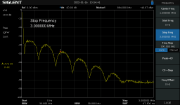
have a closer look at the spectra I did with an AudioPresicion APx555 and my Siglent RF Analyser.
Behringer runs with 48 kHz sample rate doing a 1 kHz sine.
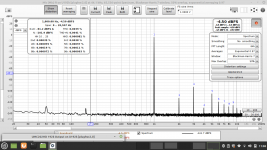
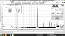
Spektrum_20K shows a 1 kHz sine and its harmonics up to 10 kHz. There is still the 13kHz spike of the 48V generator (L4 is loaded).
Spektrum_40k shows the same. The noise floor starts rising around 26 kHz. This is called noise shaping. Moving the noise from lower frequency to higher where it can be easily filtered.
Spektrum _1M shows the noise shaping up to 1.2MHZ.
Spectrum_UMC202HD1 is the same measured with my Siglent.
Spectrum_UMC202HD3 shows it up to 3 MHz.
My conclusion: The CS4272 is working fine. You just need a filter starting above 20 kHz.
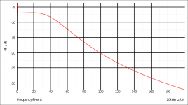
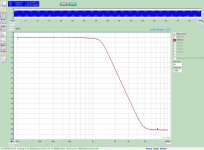
I simulated the filter from the datasheet. Here is the plot.
Alfred
have a closer look at the spectra I did with an AudioPresicion APx555 and my Siglent RF Analyser.
Behringer runs with 48 kHz sample rate doing a 1 kHz sine.
Spektrum_20K shows a 1 kHz sine and its harmonics up to 10 kHz. There is still the 13kHz spike of the 48V generator (L4 is loaded).
Spektrum_40k shows the same. The noise floor starts rising around 26 kHz. This is called noise shaping. Moving the noise from lower frequency to higher where it can be easily filtered.
Spektrum _1M shows the noise shaping up to 1.2MHZ.
Spectrum_UMC202HD1 is the same measured with my Siglent.
Spectrum_UMC202HD3 shows it up to 3 MHz.
My conclusion: The CS4272 is working fine. You just need a filter starting above 20 kHz.
I simulated the filter from the datasheet. Here is the plot.
Alfred
Attachments

Thanks for that! The datasheet filter -which I've built- seems to have a shallower roll off yet I confirm it is effective. So I would think that the noise to be addressed comes from quite high frequency. If I understand correctly, the noise shaping function relates to the ADC part isn't it? So this might get upset with the output of the DAC no matter the very low magnitude? Just amateur's speculations...
Those bumps are indeed related to noise-shaping as I mentioned in a recent previous post. You can see them on a scope too.
Otherwise, I agree with Alfred about the need to look at higher frequencies despite audio band being a much lower range. Components can deviate from their normal behaviour when exposed to those interferences and harmonics.
Nice demo on the sine wave using the filter, @lykkedk.
Otherwise, I agree with Alfred about the need to look at higher frequencies despite audio band being a much lower range. Components can deviate from their normal behaviour when exposed to those interferences and harmonics.
Nice demo on the sine wave using the filter, @lykkedk.
Hi all,
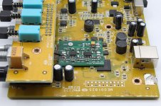
just want to show how a filter cleans a square wave: From a conversation with Jesper.
To show you the effect of the 1 KHz low pass filter I use a 960 Hz square wave.
A perfect square wave with 50% duty cycle has only odd harmonics. Their level is 1/3 for 3 times the base frequency, 1/5 for 5 times etc.
The even harmonics are pretty low.
Picture Square Wave
On top there is a scope picture of the square wave. THD is -8.3 dBc
Using this filter:
Picture of the filter response
you will get this:
Picture of the filtered Square
It looks like a sine now, THD is 67 dBc.
Alfred
Attachments


Morning here 😊
This could be hard to explain what i intend to do here, as i'am no native English guy... so i will try to be as much clear as possible.
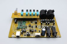
I did two mod's on my UMC now.
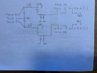
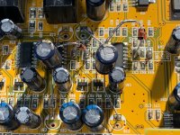
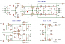
1. Mod was YashN's preamp.-bypass mod on INPUT B(X7) - C81 direct to C35 on ADC BUFFER (direct / bypass) input on AINB_ADC.
2. I did the same mod, but with INPUT B(X7) - C78 direct to C34 on ADC BUFFER (direct / bypass) input on AINA_ADC.
What i can do now is:
(MIC input R selected on REW) TRSB_T ---> (direct) ---> AINB_ADC and have some good measurement's
(MIC input L selected on REW) TRSB_R ---> (direct) ---> AINA_ADC and have some good measurement's
BUT, i expected that i could use both TRSB_T & TRSB_R without selecting different input in REW (MIC L or R)
This is not the case! ((But as i use Linux ALSA it might be possible to route the INPUT L to INPUT R)) - Did not dig into this yet, i will eventually ask phofman.
If it was the case that both input's was routed into both AINA_ADC & AINB_ADC i would have tried measuring between XLR pin 2 & 3, giving maybe even better results.
The XLR input's are going into the (now empty "+") where C34 & C35 used to be (i did verify this with my scope) - But again i have to physically and selecting the input combo (jack/XLR) L or R for this.
All this lead to the conclusion that the input's on the "internal" ADC BUFFER are only useable when selecting the corresponding MIC INPUT in REW.
If it was possible i would have removed resistor R67 and R69, routing XLR input directly to empty pad's on C34 & C35 (in series with an 47uF cap)
Am i crazy guy's 🙄
Comment's are welcome very much...
Jesper.
This could be hard to explain what i intend to do here, as i'am no native English guy... so i will try to be as much clear as possible.
I did two mod's on my UMC now.
1. Mod was YashN's preamp.-bypass mod on INPUT B(X7) - C81 direct to C35 on ADC BUFFER (direct / bypass) input on AINB_ADC.
2. I did the same mod, but with INPUT B(X7) - C78 direct to C34 on ADC BUFFER (direct / bypass) input on AINA_ADC.
What i can do now is:
(MIC input R selected on REW) TRSB_T ---> (direct) ---> AINB_ADC and have some good measurement's
(MIC input L selected on REW) TRSB_R ---> (direct) ---> AINA_ADC and have some good measurement's
BUT, i expected that i could use both TRSB_T & TRSB_R without selecting different input in REW (MIC L or R)
This is not the case! ((But as i use Linux ALSA it might be possible to route the INPUT L to INPUT R)) - Did not dig into this yet, i will eventually ask phofman.
If it was the case that both input's was routed into both AINA_ADC & AINB_ADC i would have tried measuring between XLR pin 2 & 3, giving maybe even better results.
The XLR input's are going into the (now empty "+") where C34 & C35 used to be (i did verify this with my scope) - But again i have to physically and selecting the input combo (jack/XLR) L or R for this.
All this lead to the conclusion that the input's on the "internal" ADC BUFFER are only useable when selecting the corresponding MIC INPUT in REW.
If it was possible i would have removed resistor R67 and R69, routing XLR input directly to empty pad's on C34 & C35 (in series with an 47uF cap)
Am i crazy guy's 🙄
Comment's are welcome very much...
Jesper.
Attachments
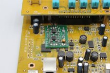
Apparently you have messed the ADC input phases. AINA + and - are for one channel and AINB + and - for the other. You are sending TRSB-T to one channel and TRSB-R to the other and that's what REW understands. The on board ADC buffer cannot accept balanced input anyway... It is a SE input to bal out converter so, TRS tip - or ring if not grounded - is all it can take.
Hi there...
Yes i see that i did take the AINA + and AINB+ input's on the ADC BUFFER... silly me!
Seem's like a dead one mod 🙄
It's not possible at all to measure between XLR pin 2 & 3 as i see it.
Anyway i did not at least destroy anything that is...
I'am going to re-enable the AINA_ADC INPUT, using an Panasonic 47uF instead of the stock one on C34 - just to try it out.
Then i will try measuring between pin 2 & 3 on the XLR input on INPUT A (X8)
Jesper.
This could have been avoided if you had asked questions in this thread before attempting any further mod. In my DM you asked how to do the Left Channel mod and I answered. You can post the whole convo. here to share with others.
Yep... your'e right...This could have been avoided if you had asked questions in this thread before attempting any further mod. In my DM you asked how to do the Left Channel mod and I answered. You can post the whole convo. here to share with others.
Nevermind through i just re-enabled the channel, so all i have is your'e preamp. bypass mod and a Panasonic 47uF instead of the stock cap. in the place where C34 was.
All is good... sry. for the misunderstanding!
Jesper.
Not sure I follow: you asked for mods for the left channel after you did something which doesn't do this. You also mentioned in the DMs that after I gave you the Left Channel mod, the mod now works. Here you're saying you reverted the Left Channel...
Yep at
I saw afterward's that it wasen't usefull... Totally unusefull...
Somehow i did think that the ADC input's was differental aka' could be used balanced, just a mistake.
Jesper.
At that time i didn't realized that i was getting it wrong.Not sure I follow: you asked for mods for the left channel after you did something which doesn't do this. You also mentioned in the DMs that after I gave you the Left Channel mod, the mod now works. Here you're saying you reverted the Left Channel...
I saw afterward's that it wasen't usefull... Totally unusefull...
Somehow i did think that the ADC input's was differental aka' could be used balanced, just a mistake.
Jesper.
Still waiting on you to post the DM content as you promised though for others to learn from.
What I'd do, is mod the Left Channel as I DMed you and use the Left Channel combo Jack separately.
This makes reverting much easier if necessary.
The two-Channel mod can be very useful with ARTA for example as it has a special mode using analysis on one channel and loopback on the second one for more in-depth calculations. Maybe REW also has this type of mode and calculations but I am not sure.
If one does select to go that route, I'd recommend matching Capacitor measurements, same brand, same type as this improves the accuracy of the calculations in those special modes.
Technically, for better accuracy, you'd want to match both channels very closely, but desoldering and matching everything along all the signal paths (so DAC path too here if you're using that as Sig. Gen. and anything along the ADC path like a preamp or filter) might not be very practical.
Last edited:
- Home
- Design & Build
- Equipment & Tools
- Behringer UMC 202HD for measurements