Cool - Nice with some options to test.
I will do... Just waiting for the pcb's to arrive from Germany.
Jesper.
So, if you are in for some experimentation, you could start from jumper wires -just remember there is no protection in this case- and compare with resistors and lamps. There should be sufficient CMRR in this circuit perhaps to go with the resistors.
I will do... Just waiting for the pcb's to arrive from Germany.
Jesper.
Hi here guy's...
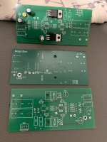
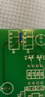
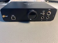
I recieved my @MagicBus balanced input board today.
If i decide to power it with batteries, should i connect the GND from the two 9vdc batteries (Connected in series) to the GND of the Behringer & ofcause the balanced input board ?
* Might be a stupid quistion i know, reason i ask is duo to the balanced connection i'am in doubt.
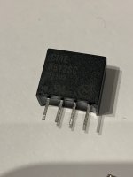
Well reason why i ask about the batteries, is that i bought two DC DC switchers (CME0512SC) - See .pdf
But i think there was a problem with one of them.
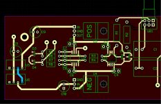
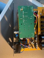
I started assembling one of the pcb's with the 3 capacitors, the two DCDC switcher and the 7809+ and 7909- regulator.
But output was only working at -9vdc, on the positive side the output was down to ca. 6vdc and input was down to 7vdc (duo to mA surge i quess?)
The one switcher got hot also.
I'am not done investigating yet, but i think one of the switchers are gone now, and i don't have any other (besides i also bought two 9vdc switchers, but then there is no room for some extra regulation)
Jesper.
I recieved my @MagicBus balanced input board today.
If i decide to power it with batteries, should i connect the GND from the two 9vdc batteries (Connected in series) to the GND of the Behringer & ofcause the balanced input board ?
* Might be a stupid quistion i know, reason i ask is duo to the balanced connection i'am in doubt.
Well reason why i ask about the batteries, is that i bought two DC DC switchers (CME0512SC) - See .pdf
But i think there was a problem with one of them.
I started assembling one of the pcb's with the 3 capacitors, the two DCDC switcher and the 7809+ and 7909- regulator.
But output was only working at -9vdc, on the positive side the output was down to ca. 6vdc and input was down to 7vdc (duo to mA surge i quess?)
The one switcher got hot also.
I'am not done investigating yet, but i think one of the switchers are gone now, and i don't have any other (besides i also bought two 9vdc switchers, but then there is no room for some extra regulation)
Jesper.
Attachments
Hi Jesper!
Let's see... If you use the metal spacer I suggested then the two boards' GND is connected and the batteries' GND could go anywhere but preferably to the small green one.
Usually, these switchers are hard to cook. I had a look at the datasheet. It's not very clear but I think they require a minimum load to operate. So, try a 560 to 1000 ohm at the outputs of both regulators. Also, keep all electrolytics no bigger than 10μF.
I appreciate your efforts on this!
Best regards
Kostas
So good...
Well i took them DC switcher's out, and "tested" them with my scope, and they seem to be working fine anyway... They deliver alone 16v from 5vdc input; look's allright.
I can't find anything regarding the uF size to use with the switcher's, but i had 100uF plugged in the pcb now, if it's a failure i have some 10uF on hand to test.
- Will investigate further, will eventually figure it out. - I had a feeling that it could be a capacitor problem!
Will also read about minimum load regulation on the switcher etc...
The idle load on the 7909 / 7809 is around 5mA is what i could find, so this should be good also i guess.
To be continued for sure 😎
Jesper.
Well i took them DC switcher's out, and "tested" them with my scope, and they seem to be working fine anyway... They deliver alone 16v from 5vdc input; look's allright.
Also, keep all electrolytics no bigger than 10μF.
I can't find anything regarding the uF size to use with the switcher's, but i had 100uF plugged in the pcb now, if it's a failure i have some 10uF on hand to test.
- Will investigate further, will eventually figure it out. - I had a feeling that it could be a capacitor problem!
Will also read about minimum load regulation on the switcher etc...
The idle load on the 7909 / 7809 is around 5mA is what i could find, so this should be good also i guess.
To be continued for sure 😎
Jesper.

I thought it was going to be the same for me as my order went to Digi-Key Canada, but no...i live in DK and Mouser have a quarter in our neigbour country Sweeden.
Good thing is that eventhrough parts are comming from the US, all tax and everything is taking care of when i pay online. -Parts are not more expensive than local parts here in DK this way. So Mouser and partly DigiKey is my freind's 🙂
And I am looking forward to your measurements of both my simple mod and MagicBus's balanced one. That would be a really interesting comparison.I'am really looking forward to test this Magic balanced board, and most are ready on my Behringer now.
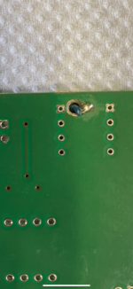
"Easy" fix for the missing GND link 😉
According to the datasheet, the specific type of DCDC switcher I have, I should use the following on the output::
68uH coil & 1uF capacitor
Minimum load 10% (12 / 63mA = 1.9Kohm ~ 1.7Kohm for 15% load)
Should i try, (is it a good idea) ? with a somewhat low C9 / C10 uF capacitor and tie resistors to them for minimum load ?
Jesper.
I have attached the datasheet in post #323 btw...
Attachments
Nice! The LC filter helps to minimize ripple when use the switcher to power directly the circuit. With post regulation, I think 10μF would be better. Try 1k resistors after the 9V regs.
I agree here...The LC filter helps to minimize ripple when use the switcher to power directly the circuit
It's datasheet is mostly based on standalone circuit.
I will do some testing.
Jesper.
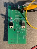
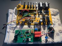
Success 🙂
100uF on DCDC switcher inputs
10uF on DCDC switchers outputs before they meet the regulator's (C9, C10)
1K5 between GND & OUT on the two regulator's.
Approx 8mA on both + & - side + the regulator's idle load, which is around 5mA... So ~13mA as idle load for now.
Output regulator, looking good enough on scope to :: -9.07VDC // +8.97VDC
Thank's for helping me so far!
Jesper.
Attachments
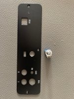
Ohh... forgot to ask!
Is is best with a LINEAR or LOGARITHMIC potentiometer here (VR1 100K)
Jesper.
Is is best with a LINEAR or LOGARITHMIC potentiometer here (VR1 100K)
Jesper.
It will also be interesting to compare the measurements here from powering with the switcher vs powering w. batteries or a Linear Reg. PSU.
My plan is, that (if) when working i will make two pcb's to put in where the 7809/7909 are now, with state of the art lt3045/lt3094.It will also be interesting to compare the measurements here from powering with the switcher vs powering w. batteries or a Linear Reg. PSU.
I did some lt3045(dual) pcb back in 2019 when i build DimDims AK4490 dac. - And the lt3045/lt3094 are really good reg's. - They can be tweaked to be even better than batteries i read.
Well... I need to put in the potentiometer, will just wait until i am sure if LOG or LIN is best to use here?
Jesper.
Attachments

Looking good! I'm afraid I don't have an answer about the pot... Both would work but what is better for dB scale? For my built I needed a four gang pot and I ordered what was available at the time but I don't recall now.
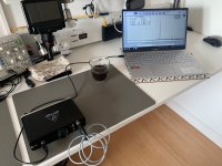
Hi here...
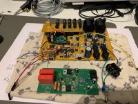
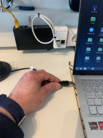
Today it's a really good day i think 😎
I Can't wait to test it for real now!
What's going to be, Ex**plod or what, when plugging in the USB ?
Jesper.
Today it's a really good day i think 😎
I Can't wait to test it for real now!
What's going to be, Ex**plod or what, when plugging in the USB ?
Jesper.
Attachments
Just kidding guy's...
Sry...
@MagicBus, i donno if you allready wrote this somewhere, but can the board accept say a voltagesving directly from an poweramp... could be 2.8v for measuring with 1W load.
For now i'am using a voltage divider and never feed more than 800mV into the Behringer.
Did some loopbacktest to see the difference between YashN's mod and this balanced input mod.
Attached here also.
Jesper.
Attachments

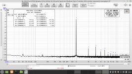
Well done! 👍 It might get better if you keep the wires to the CS4272 as short as possible. But already very good I think. For comparison I attach a loop of my soundcard. And if I understand correctly this is with the 33k resistors isn't it?
You won't need that voltage divider any more. It can forgive a lot now. DC as high as C1/C2 can take and AC a few tenths easily. But I suggest you always start with the pot turned down and slowly turn up until you reach close to say -3dB. Then you will have a picture of the dynamic range and see what happens really low. It would be interesting to start with something known for reference like DCG3.🙂
You won't need that voltage divider any more. It can forgive a lot now. DC as high as C1/C2 can take and AC a few tenths easily. But I suggest you always start with the pot turned down and slowly turn up until you reach close to say -3dB. Then you will have a picture of the dynamic range and see what happens really low. It would be interesting to start with something known for reference like DCG3.🙂
Attachments

Yes...
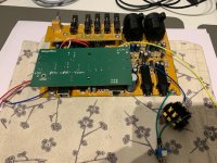
It is fine, and really good work MagicBus, getting it all to fit like that into the Behringer enclosure is something 👍
I did some two hour test to see if something went unstable or hot or like, everything looking good.
* Looks like it's working as expected, saying i did not really try some real amp. testing yet!
100K LOG / AUDIO taper is working very good in this setup btw...
Is it correct to connect like this when i make cables ? ::
SE amp. GND ---> R on TRS balanced input
SE amp. + --------> T on TRS balanced input
GND on TRS are not connected to anything.
I will do some more testing whitin next day's
Jesper.
It is fine, and really good work MagicBus, getting it all to fit like that into the Behringer enclosure is something 👍
- I know about the wire's, but i keept them longer while i was testing before putting it all together.
- Yes i use 33K / 3W resistors for now. - I needed to see if it was working.
I did some two hour test to see if something went unstable or hot or like, everything looking good.
* Looks like it's working as expected, saying i did not really try some real amp. testing yet!
100K LOG / AUDIO taper is working very good in this setup btw...
Is it correct to connect like this when i make cables ? ::
SE amp. GND ---> R on TRS balanced input
SE amp. + --------> T on TRS balanced input
GND on TRS are not connected to anything.
I will do some more testing whitin next day's
Jesper.
- Home
- Design & Build
- Equipment & Tools
- Behringer UMC 202HD for measurements