Very nice Jesper! Yes, you connect the DUT like this. That's the idea with this scheme, it disregards GND.
Thank's both...
I must say again, that the mod Magic did is impressive, also getting it to fit inside the enclosure is perfect 👍
I had some spare time, duo to some extra work i had recently on my job, so i had some two day's to play with this thing.
I need to study more regarding what we can see on the RTA. I'am not sure howto read the numbers correct.
As i see it, it's about having a soundcard with a lower noisefloor (incl. THD's) than the DUT.
When this is avalible we better se everything.
But again, i really need to study...
Jesper.
Gentlemen 🙂
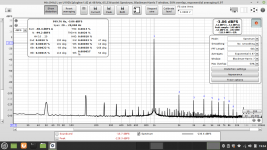
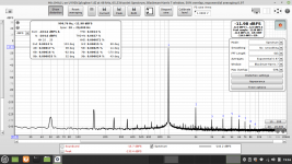
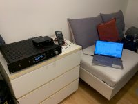
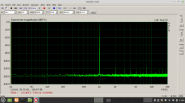
As suggested i did try measuring my Salas DCG3. (Picture from inside attached)
This is not a "real" DCG-3; the PCB's are handdrawn, but i used quality component's all the way including high quality transformers.
EDIT :: Preamp. is loaded with 10Kohm between GND and + out during measurements.
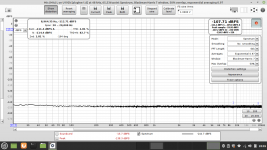
I was never before capable of plotting anything like this without a big forrest of spikes laying all over at >100dB
Sure there are some spikes existing now, but i had the Behringer on top of the preamp, and only using the "internal" 1KHz generator.
(I don't have any external generator right now)
This is a real success for me this.
Jesper.
As suggested i did try measuring my Salas DCG3. (Picture from inside attached)
This is not a "real" DCG-3; the PCB's are handdrawn, but i used quality component's all the way including high quality transformers.
EDIT :: Preamp. is loaded with 10Kohm between GND and + out during measurements.
I was never before capable of plotting anything like this without a big forrest of spikes laying all over at >100dB
Sure there are some spikes existing now, but i had the Behringer on top of the preamp, and only using the "internal" 1KHz generator.
(I don't have any external generator right now)
This is a real success for me this.
Jesper.
Attachments

When you did the comparo between Single-Ended and the Balanced, was the Balanced with the switcher already installed?
Hi YashN...
Yes the board was inside and connected during the two loopback test's.
But i remember that the number's was identical without it, with your'e mod only.
The number's between the two mod's are allmost identical, giving the MagicBoard a little better noisefloor.
* But this was not thoose insanly low number's i was looking for, it was to do the plotting without the forrest of spikes, and it look's to me like it is a success.
Jesper.

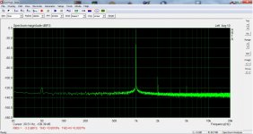
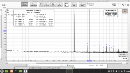
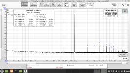
I'm not selling myself as a specialist so these are just my thoughts. Attached my DCG3 measured with my soundcard/ARTA delivering 2,6V to 600 ohm headphones. I've noticed before that REW shows a higher dynamic range -the distance from the -3dB peak to the floor. Unfortunately I can't take advantage of REW capabilities in my system and never got a clear explanation for this... Anyway, I think this is only academical because the important info is there. The 50Hz and 2kHz peaks in both graphs are more or less at the same level -distance from the -3dB peak. There are these 150, 250Hz etc which normally indicate intermodulation between 50 and 100Hz but there is no 100Hz here to justify this. Apparently, REW understands that so the final figures for THD% and THD+N% are marginally better than mine. I don't think ARTA would be so forgiving with these spikes...Gentlemen 🙂
As suggested i did try measuring my Salas DCG3. (Picture from inside attached)
This is not a "real" DCG-3; the PCB's are handdrawn, but i used quality component's all the way including high quality transformers.
EDIT :: Preamp. is loaded with 10Kohm between GND and + out during measurements.
I was never before capable of plotting anything like this without a big forrest of spikes laying all over at >100dB
Sure there are some spikes existing now, but i had the Behringer on top of the preamp, and only using the "internal" 1KHz generator.
(I don't have any external generator right now)
This is a real success for me this.
Jesper.
All in all to my eyes it seems absolutely usable! And we are talking about cheap SMPS, LM78XX regs and resistive current limiters. Together with UMC202 a total less than the cost for the USB to I2S converter for my soundcard... Give the masses performance!
Attachments
Some more thoughts. Internal generator is better unless you have a state of the art external. Also, you will notice that the input pot is playing its role adding noise depending on different level settings. An expensive switch attenuator would do better but that defeats the purpose of this project I think.
Hi all,
I just had a look at MagicBus ADC driver schematics.
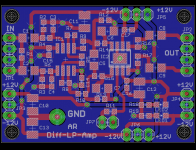
A while ago (before I even knew the Behringer) I did this differential filter board for another application. Might be used to drive the ADC.
The diff amp can be a second order low pass filter. With a small modification the feedback can be changed behind the output resistors.
I just had a look at MagicBus ADC driver schematics.
A while ago (before I even knew the Behringer) I did this differential filter board for another application. Might be used to drive the ADC.
The diff amp can be a second order low pass filter. With a small modification the feedback can be changed behind the output resistors.
Attachments

Hi here.
I am in to try replacing the two 33K / 3W resistors, with the 606-CM120MB bulp.
What i'am trying to figure out is how can i see when i should NOT apply any more juice into the Behringer (voltage etc...)
Is it just by observing the dB scale on the RTA in REW, stopping when reaching ~-3dB ??
Jesper.
I am in to try replacing the two 33K / 3W resistors, with the 606-CM120MB bulp.
What i'am trying to figure out is how can i see when i should NOT apply any more juice into the Behringer (voltage etc...)
Is it just by observing the dB scale on the RTA in REW, stopping when reaching ~-3dB ??
Jesper.
Hi Jesper,
It depends on the settings in the digital domain too. Especially for REW and mostly in ASIO mode, I found that it takes control of these settings and generally keeps levels low. YMMV though... But if this happens, then no matter how much you turn up the input pot, it won't go full scale. The safest indicator of overloading/clipping is a rapid increase of odd order harmonics. This is to know when you have pushed too much the analog circuit before the ADC. Regarding the ADC, it should be fine up to 0dB and suddenly clip after that.
The input protection is there to save the circuit from such a case.
Hi Folks,
Newby here, and as matter of fact, this is my very first post on diyAudio. Before getting to the topic of this thread, please allow me to introduce myself first.
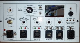
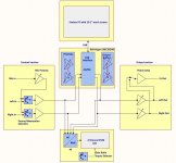
I’m a professional electronic engineer with almost 38 years of experience in designing all sorts of electronic circuits. As a hobby, I am interested in audio electronics. Over the past few years, I have become more interested in doing microphone modifications. In order to test these modifications, you’ll want an audio analyzer. But I found even used AP or R&S analyzers were way too expensive. On the other hand, I was tired of setting up and calibrating a measurement system around a sound card and laptop. So I decided to build a self-contained analyzer using a Behringer UMC202HD audio interface, a built-in computer with 10.1” touchscreen LCD etc. Once finished, I will present the design as an open-source project on my website. The website (modimications.com) is not yet online and will not be live anywhere soon, but here you’ll get a sneak preview of what my diy audio analyzer involves and which modifications I applied to the UMC202HD. Attached, you will find a block diagram of the analyzer and a picture of a partly assembled front panel. This gives you roughly an idea of the hardware capabilities. I haven’t decided yet on which software to use, but most likely REW, ARTA, and maybe some others as well.
Actually, I thought I was more or less ready with all the modifications when I stumbled across this thread and found some interesting material that inspired me to open the UMC202HD again and work on some more mods. Let me start with all the flaws I found out already and which I changed.
Cheers, Jan
Newby here, and as matter of fact, this is my very first post on diyAudio. Before getting to the topic of this thread, please allow me to introduce myself first.
I’m a professional electronic engineer with almost 38 years of experience in designing all sorts of electronic circuits. As a hobby, I am interested in audio electronics. Over the past few years, I have become more interested in doing microphone modifications. In order to test these modifications, you’ll want an audio analyzer. But I found even used AP or R&S analyzers were way too expensive. On the other hand, I was tired of setting up and calibrating a measurement system around a sound card and laptop. So I decided to build a self-contained analyzer using a Behringer UMC202HD audio interface, a built-in computer with 10.1” touchscreen LCD etc. Once finished, I will present the design as an open-source project on my website. The website (modimications.com) is not yet online and will not be live anywhere soon, but here you’ll get a sneak preview of what my diy audio analyzer involves and which modifications I applied to the UMC202HD. Attached, you will find a block diagram of the analyzer and a picture of a partly assembled front panel. This gives you roughly an idea of the hardware capabilities. I haven’t decided yet on which software to use, but most likely REW, ARTA, and maybe some others as well.
Actually, I thought I was more or less ready with all the modifications when I stumbled across this thread and found some interesting material that inspired me to open the UMC202HD again and work on some more mods. Let me start with all the flaws I found out already and which I changed.
- The audio circuits were powered by just 4.5V, which severely limited the already low headroom of the op-amps and codec. This was especially noticeable at signals above -6 dBFs, where THD was rising sharply. At first, I assumed this was caused by voltage drops in the USB cable, but the input voltage on the UMC202HD USB input measured exactly 5.0V. I then followed the internal power supply filter circuit and ended up finding a PS73201 LDO IC (IC3), which was set to an output voltage of 4.5V. According to the datasheet, the minimum operating voltage for the CS4272 equals 4.75V, so having the internal power supply voltage set to 4.5V should be considered a serious design flaw IMHO. This also explains that whatever external power supply you attach to this board, the internal power supply will always remain a meager 4.5V. On the other hand, I can understand why Behringer chose this approach: USB voltages can be as low as 4.75V, at least theoretically. Add to that some cable losses and the minimum drop-out voltage of the LDO and in the end, 4.5V seems quite reasonable. But I have only one computer attached to the UMC202HD and that one supplies a neat 5V, so I decided to change the internal voltage to 4.9V. The output voltage of the LDO is determined by R16 and R17. If I remember well, I changed R17 to 9k1//270k to get approximately 4.9V. If you want to use other resistor values, just have a look at the PS73201 datasheet to calculate the resistor values. I also experimented with a capacitor parallel to R16 to improve the LDO transient response, but it made the LDO unstable. Anyway, THD at high input levels dropped significantly when the internal power supply was raised to 4.9V.
- Many UMC202HD suffer from a nasty spike in the 8 to 30 kHz range. Mine too at 17 kHz. As we all know in the meantime, this is caused by the 48V boost converter. As I planned to use an external 48V linear supply anyway, I didn’t mind killing the converter.
- As you can see in the block diagram, I bypassed the input and output circuits. The input circuits of my analyzer will be replaced by my own design, with continuously variable and stepped attenuators/amplifiers covering sensitivities between 2mV full scale and 200V full scale. The high impedance balanced 200mV to 200V line inputs will have overvoltage protection to levels > 200V. The outputs of my circuits will connect directly to R34 and R40 of the ADC buffer (with C34 and C35 removed). I removed the Direct Monitor switch and took the DAC output signal from the center pins of this switch. More on the DAC output buffer later.
- I replaced IC8 and IC13 with OPA1664 opamps. These have slightly lower noise, lower THD and a slightly wider common-mode input voltage range. Not a game-changer, but it helps.
- Having done all the above modifications, I was ready to assemble all the PCBs I had designed. I started with the output boards and I was happy with them until I discovered this thread and opened bobun’s schematic in post #101. (Thanks bobun, I always found reverse engineering a PCB a tedious job.) At first I thought: nooo, this just cannot be true, bobun must have made mistake… But I checked the schematic, checked it again and again, but the ADC and DAC buffers are indeed exactly as bobun drew them. The only minor flaw in the schematic I could find included the values of C65 and C73. They are actually 47pF, at least in my unit. But if I’m not mistaken, bobun just used a default value of 470pF for all caps, didn’t he? Anyway, in can confirm that C42, C57, C58 and C43 are indeed 470pF.
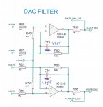
But now back to the basic circuit designs which are one big design flaw. Let’s start with the DAC buffer, or DAC Filter as bobun named it. Well, actually it’s just a buffer without any low-pass filtering, except for the compensation capacitors C65 and C73. An Audio DAC without low-pass output filter: can you imagine one…? So this is why I measured 45mV RMS output noise. Fortunately, most of it out of band, but still. So I wanted to add some filtering, but wanted a minimally invasive solution. Now Alfred came up with a nice 3d order filter, but it would add another stage introducing distortion, so I decided not to use this filter. Or I could have copied the recommended output filter circuit from the datasheet, but that would certainly not meet my definition of a “minimally invasive” solution. So I decided to split the filter in three sections with minimal impact on the stock UMC202HD design.
The first -6dB/oct low-pass stage is actually the existing DAC Buffer, albeit slightly modified. I replaced R92 and R55 by 4k7 resistors as both outputs seemed to have the same output levels. So I did not see a reason to have different gains for the inverting and non-inverting signals. Secondly, I replaced C65 and C73 by 390pF NP0/COG caps. And I piggy-backed 390pF caps on top of R43 and R50. Voila, my first filter stage was ready and it reduced the noise to just 19mV from 45mV. Cut-off frequency equals ~87kHz.
The second stage is just a passive RC filter on the output of the DAC buffer. I changed R98 and R99 to 100 Ohms to reduce attenuation by the external output buffer. That buffer has 10k input potentiometer and a 1k output resistor would attenuate the signal by 1 dB. These 100 Ohm output resistors are followed by 4.7nF capacitors to GND, which adds a pole at ~340kHz to filter any residual RF noise. It reduced noise by another 2mV or so.
The third and last filter stage consists of an inverting buffer on my output stage PCBA where I increased the compensation cap to 100pF, shifting its pole to ~80kHz. Circuit and measurement data to be published later when I finalized the complete analyzer. All filter stages together create a ~0.5dB drop at 20kHz, which I consider acceptable. For sure not as good as Alfred’s filter, but it saved me a lot of work.
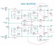
- And now on the ADC buffer/filter stage. At first sight, it looks quite similar to the proposed filter from Cirrus Logic, but on closer inspection, all the feedback resistors appeared to be connected to the wrong side of output resistors R28, R45, R31 and R46. Either the Behringer engineer had a serious hangover when copying the Cirrus Logic circuit into his CAD system, or he was a **** cocky engineer who thought he could re-invent a better wheel than Cirrus Logic already did for him. Anyway, I will change the circuit to the Cirrus Logic design. This is quite easy to do:
- Cut the traces at the red crosses in the attached circuit diagram.
- Replace all 1k output resistors with 91 Ohm.
- Replace C29 and C33 with 2n7 NP0/COG caps.
- Short R38 and R39. Not needed, at least not when the op-amp has been replaced by an OPA1664. And I think even the AD8694 can do without, because common-mode distortion due to varying input capacitances is generally only significant with high input resistances.
- Remove R26 and R32.
Admittedly, I haven’t tested this yet as I’m still waiting for some parts to come in. But as this is a proven circuit, I guess it will work. Circuit diagram attached.
For those who want to learn more about the basics of this filter topology, I would recommend reading this article: https://www.edn.com/audio-adc-buffer-design-secrets-interfacing-to-audio-adc-sampling-circuits/
Cheers, Jan
Thanks for posting this! Interesting info! Only one comment if I may about the ADC buffer. I can't tell about OPA1664 but I've already tried this exactly mod on the AD8694 and it was catastrophic... Everything is in the early posts of this thread.
Jan...
That's pretty cool what you are doing 🙂
I'am interessted in the 4.5vdc ---> 4.9vdc (or 4.8vdc) mod you did, giving the CS4272 more headroom ::
I can't see to calculate with the values you give through (9.1K / 270K) - For an approx. 4.8vdc i calculate (75000+25100)/25100*1,204 (See page 13 of datasheet)
Well it's something to figure out, and ofcause we can use a wide range of programming resistor's to archive the desired voltage.
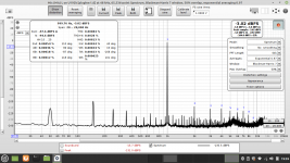
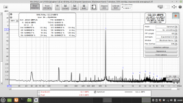
Another thing is that i tried with some trial and error to measure an loopback with ARTA running in virtual mode on my Linuxbox here (WINE).
I finally got two identical measurement's, which i will show here.
Please take this with a grain of salt, as i did not tweak the driver's and the resolution does not run on the same bit's (16, 32 etc...) running WINE vs. native Linux audio.
But fun to see 🙂
Jesper.
That's pretty cool what you are doing 🙂
I'am interessted in the 4.5vdc ---> 4.9vdc (or 4.8vdc) mod you did, giving the CS4272 more headroom ::
I assume you are ref. to this datasheet TPS732xxThe output voltage of the LDO is determined by R16 and R17. If I remember well, I changed R17 to 9k1//270k to get approximately 4.9V. If you want to use other resistor values, just have a look at the PS73201 datasheet to calculate the resistor values.
I can't see to calculate with the values you give through (9.1K / 270K) - For an approx. 4.8vdc i calculate (75000+25100)/25100*1,204 (See page 13 of datasheet)
Well it's something to figure out, and ofcause we can use a wide range of programming resistor's to archive the desired voltage.
Another thing is that i tried with some trial and error to measure an loopback with ARTA running in virtual mode on my Linuxbox here (WINE).
I finally got two identical measurement's, which i will show here.
Please take this with a grain of salt, as i did not tweak the driver's and the resolution does not run on the same bit's (16, 32 etc...) running WINE vs. native Linux audio.
But fun to see 🙂
Jesper.
Attachments

I figured the voltage programming out.
I found a good picture i took along the way, where the LDO can be seen clearly.
The R17 is "SMD 43C" = 27400ohm and R16 is "SMD 01C" = 10000ohm
Putting thoose numbers into the calculation gives :
(27400+10000)/10000*1,204 = 4.5vdc
(The CS4272's datasheet (as Jan wrote) state's minimum 4.75vdc for sure)
When using say 9100ohm instead of the 10000ohm we end up around 4.8vdc.
DataSheet recommends that R1||R2 are equal to 19000ohm, and my calculation for 4.8vdc gives an parallel resistance of 6800ohm... but properly doesent matter ?
If we use R17(R1) = 75000ohm and R16(R2) = 25000ohm, we end up with R1||R2 near 19000ohm with 4.8vdc out -- Just a thought!
Jesper.
@MagicBus, post #355: I finished modding one input channel as described. No signs of spontaneous oscillations, nor overshoot when applying a square wave... I'll modify the other channel later and post some THD plots.
@jesper: I noticed I also changed R16. It is now 27k. With R17 being equal to 9k1 parallel to 270k, you'll get 4.9V. Calculation: 9k1//270k = 8803 Ohm. Vout = 1.204 * (8803 + 27k)/8803 = 4.9V.
@jesper: I noticed I also changed R16. It is now 27k. With R17 being equal to 9k1 parallel to 270k, you'll get 4.9V. Calculation: 9k1//270k = 8803 Ohm. Vout = 1.204 * (8803 + 27k)/8803 = 4.9V.
Yep... I think i need to explain better, so here it goe's :@jesper: I noticed I also changed R16. It is now 27k. With R17 being equal to 9k1 parallel to 270k, you'll get 4.9V. Calculation: 9k1//270k = 8803 Ohm. Vout = 1.204 * (8803 + 27k)/8803 = 4.9V.
The datasheet tells me this :
NOTE: VOUT = (R1 + R2)/R2 * 1.204́
R1 || R2 @ 19kohm for best
accuracy.
As i read it, the programming resistor's should be near 19Kohm in parallel calculated for best performance.
The stock values of Behringer (R16 & R17) are 10K & 27.4K which gives somewhat 7.2K which is not near 19'K
Using 75K and 25K gives R1 || R2 ~19K
And 75K as R1 & 25K as R2 gives 4.8vdc as i would like.
Hope i got it right explained now 🙂
Jesper.
- Home
- Design & Build
- Equipment & Tools
- Behringer UMC 202HD for measurements