Yep, indeed. With OPA1664. I banned the AD8694s when modding the UMC202HD in September or October last year and they will not return. I modded the other ADC buffer too now. See attached pictures for the results. Shortest possible loopback from IC13 DAC output to IC8 ADC input buffer. The first picture shows the RTA with the stock ADC buffer and the second one is with ADC buffer as specified by Cirrus Logic. I think it's quite obvious the Behringer solution (or design flaw) is inferior to the Cirrus Logic circuit. DAC output level was set to -6dBFs. Output filter -6dB/oct as discussed before. I'm satisfied with the results, so I closed the UMC202HD and will continue my work on the external PCBAs.I assume that is with OPA1664 isn't it? Very interesting! Anxious to see how it goes.
Basically, I totally agree with your calculations. And yes: Behringer (and me too) did not follow the datasheet guidelines. But in this case, I think less-than-ideal resistor values can be justified given the fact that the accuracy of the set voltage is only very little affected. Let's calculate the maximum error for the Behringer case. From the datasheet, we read that the maximum FB input current to the error amp equals 0.45uA. In the Vout formula below Table .1 from the datasheet, TI seems to have taken a FB input current into account which equals 1.204V - Vfb = 1.204 - 1.200 = 4mV. This corresponds with a FB input current of 4mV/19k = 0.21uA. Now the maximum additional offset error introduced by the non-ideal input resistances equals (19k - 10k//27k4) * (0.45uA - 0.21uA) = 1.8 mV. Multiplied by the gain as defined by resistors R16 and R17 yields a maximum output error of 1.8*(27.4k+10k)/10k = 6.6mV. Unless you are (ab)using the LDO output voltage as a reference voltage, this error is very small compared to the 4.5V output voltage.Yep... I think i need to explain better, so here it goe's :
The datasheet tells me this :
NOTE: VOUT = (R1 + R2)/R2 * 1.204́
R1 || R2 @ 19kohm for best
accuracy.
As i read it, the programming resistor's should be near 19Kohm in parallel calculated for best performance.
The stock values of Behringer (R16 & R17) are 10K & 27.4K which gives somewhat 7.2K which is not near 19'K
Using 75K and 25K gives R1 || R2 ~19K
And 75K as R1 & 25K as R2 gives 4.8vdc as i would like.
Hope i got it right explained now 🙂
Jesper.
I don't know why Behringer chose other than ideal resistor values, We can only guess. A valid reason could have been that they use the same resistors elsewhere in the design (just a guess). The lower the number of different parts, the lower the inventory and assembly costs. In my particular case, the 27k, 9k1 and 270k resistors were values I had in stock. If I had to design the circuit from scratch and had my Mouser shopping basket filled with >50 Euros of parts, I would probably have chosen the ideal values and ordered those along with the other parts. So all in all, in my opinion, we can forgive Behringer this "design flaw". But we can definitely not forgive them for the flawed ADC and DAC filters.
Jan

That's an impressive opamp indeed! Stable with capacitive load and not a sign of 50Hz noise! Moreover, going to full scale, I never managed anything higher than -8dB with the stock opamps. I've been always confused with CS4272 datasheet stating that full scale could be achieved with 1,13* VA so I never thought that VA<5V wouldn't work. Nice work!
Thanks MagicBus! But a lot of good work has been done by the contributors to this thread also, which inspired me too. Nice to see how we can learn from eachothers work.
Admittedly, I'm positively surprised too about the actual performance of the cheap CS4272 codec. No need for me at least to try and get hold of a (broken) SSL2 with AKM chip.
Those TI Soundplus series opamps do miracles, indeed. They are my favourite opamps. For my Audio Analzer project, I'll be using two OPA1612 in parallel in the mic preamp circuit, OPA1604 for the line input INA circuit and OPA1641 and OPA1604 in the output buffer. And no, I don't own TI shares... 😉
Welcome jp8,
That's quite an in-depth diagnosis and set of fixes for the interface, thanks for sharing.
I should try that resistor adjust for the LDO.
That's quite an in-depth diagnosis and set of fixes for the interface, thanks for sharing.
I should try that resistor adjust for the LDO.
I sure agree, that't it's good to have some more informations, about the Behringer setup. Thank's Jan.
Well i opened up my box yesterday, and unfortunately found that i only have 4.81vdc on my LDO inside.
There aren't much room for an 40mV regulation here, donno if it's worth a try?
* Actually i have 60mV down to MIN analog supply for the CS4272
Jesper.
Well i opened up my box yesterday, and unfortunately found that i only have 4.81vdc on my LDO inside.
There aren't much room for an 40mV regulation here, donno if it's worth a try?
* Actually i have 60mV down to MIN analog supply for the CS4272
Jesper.
I've been thinking about this. I had to remember what I've done with this soundcard. Amongst other things I had tried an add on buffer with DC boosters like the one Jesper built only it was a replicate of CS4272 app notes SE to BAL converter using NE5532. This way it did reach to 0dB full scale with the lowish VA and this is verified by Jesper with the new buffer. So, I think it is valid that the CS4272 needs 1,13*VA input signal to do that as the datasheet suggests. Meaning that it will need 5,6V input when VA=5V but less is also working. The problem with that NE5532 buffer was high distortion, significantly higher than this opamp justifies. Although it is famous for stability, simply it couldn't drive the ADC. As I've said many times, the capacitor at the input of the ADC makes all opamps feel uncomfortable. Behringer's EEs seem to have spot that and cured it by adding resistors between AD8694 and CS4272 so it would be unfair to underestimate their work. Actually it seems that Cirrous Logic EEs are those who missed the point after all... In their app notes they say that the compensation caps around the buffer are there for anti aliasing purposes but no, it goes the other way around. It is the opamp that need to be protected by shaping its phase margin so to avoid oscillation. And this is the critical point with ADC buffers. For example, Alfred's circuit in post #350 from the looks of it should be a high quality preamp but it is not optimized for ADC buffer. If you have a look at LME49724 datasheet page #17 it says that it would need compensation specifically tuned for this job.
All that said, I need to try this OPA1664, it seems so good.
All that said, I need to try this OPA1664, it seems so good.
Hmm, that's not a lot of headroom, indeed. Too little, I'm afraid. Any chance you can get a higher voltage on the board? E.g. by using a shorter USB cable or with thicker wiring. Or else, use an USB isolator an remove the DC/DC converter. Then connect a decent linear 5.1V to 5.25V power supply to the DC/DC converter output terminals. I bought one from Aliexpress and wanted to test this, but haven't done so yet. Search for ADUM3160 on Aliexpress.I sure agree, that't it's good to have some more informations, about the Behringer setup. Thank's Jan.
Well i opened up my box yesterday, and unfortunately found that i only have 4.81vdc on my LDO inside.
There aren't much room for an 40mV regulation here, donno if it's worth a try?
* Actually i have 60mV down to MIN analog supply for the CS4272
Jesper.
R28 and R31 in the UMC202HD decouple the cap from the opamp outputs, similarly to R5 an R6 in the LME49724. So CL engineers certainly did not miss this important fact. It's the Behringer EE who did not exactly copy the CL schematic and connected the feedback resistors to the wrong side of R28 and R31. If you read the EDN article, you'll see the CL is a commonly used ADC buffer and should work with many opamps.I've been thinking about this. I had to remember what I've done with this soundcard. Amongst other things I had tried an add on buffer with DC boosters like the one Jesper built only it was a replicate of CS4272 app notes SE to BAL converter using NE5532. This way it did reach to 0dB full scale with the lowish VA and this is verified by Jesper with the new buffer. So, I think it is valid that the CS4272 needs 1,13*VA input signal to do that as the datasheet suggests. Meaning that it will need 5,6V input when VA=5V but less is also working. The problem with that NE5532 buffer was high distortion, significantly higher than this opamp justifies. Although it is famous for stability, simply it couldn't drive the ADC. As I've said many times, the capacitor at the input of the ADC makes all opamps feel uncomfortable. Behringer's EEs seem to have spot that and cured it by adding resistors between AD8694 and CS4272 so it would be unfair to underestimate their work. Actually it seems that Cirrous Logic EEs are those who missed the point after all... In their app notes they say that the compensation caps around the buffer are there for anti aliasing purposes but no, it goes the other way around. It is the opamp that need to be protected by shaping its phase margin so to avoid oscillation. And this is the critical point with ADC buffers. For example, Alfred's circuit in post #350 from the looks of it should be a high quality preamp but it is not optimized for ADC buffer. If you have a look at LME49724 datasheet page #17 it says that it would need compensation specifically tuned for this job.
All that said, I need to try this OPA1664, it seems so good.
Cheers, Jan
I understand, thanks! Cirrus Logic buffer should be universal regarding stability but not all opamps will deliver their best distortion figures with this generic scheme. Already checked for AD8694 and NE5532. LME49724 manufacturer also makes a comment on this. It seems that OPA1664 is made to fit there naturally...
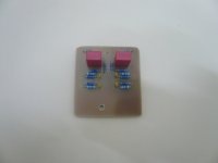
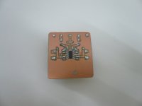
Hey guy's... 🙂
I had some conversation with Victor (the guy which are selling the 1KHZ osc.)... I bought one from him recently; today i did some test's with it.

I had as usually some problems with setup picking all kind's of spikes up (mainly 50Hz + 100Hz etc...)
But with Victor's oscillator i can connect the Behringer shield/GND to the Victor's chassis i build the thing into.
When this connection is established, everything is very prone to noise pickup, i can even leave the laptop psu in the mains outlet, without no noticeable noise measured...
Fortunately i didn't had the time yet to do some real DUT measurement's, but i thought that i would like to show this.
I also build an LM317 psu, which i build into an old switcher supply i had.
The LM317 are somewhat stressed, giving it near it's maximum of +40vdc on the input, having some pretty nice +34.8vdc out for the oscillator.
Attached some pictures showing both battery powered and my LM317 supply with the Victor's.
Jesper.
I had some conversation with Victor (the guy which are selling the 1KHZ osc.)... I bought one from him recently; today i did some test's with it.
I had as usually some problems with setup picking all kind's of spikes up (mainly 50Hz + 100Hz etc...)
But with Victor's oscillator i can connect the Behringer shield/GND to the Victor's chassis i build the thing into.
When this connection is established, everything is very prone to noise pickup, i can even leave the laptop psu in the mains outlet, without no noticeable noise measured...
Fortunately i didn't had the time yet to do some real DUT measurement's, but i thought that i would like to show this.
I also build an LM317 psu, which i build into an old switcher supply i had.
The LM317 are somewhat stressed, giving it near it's maximum of +40vdc on the input, having some pretty nice +34.8vdc out for the oscillator.
Attached some pictures showing both battery powered and my LM317 supply with the Victor's.
Jesper.
Attachments
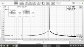
Ofcause...
I just did.
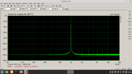
ARTA eats a little more juice, so full scale on your'e balanced Magic 🥷 box, end up with -2.5dB
I tried different input from the Victor's, and the attached picture is the best i could get.
Jesper.
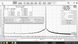
EDIT :: Missing Setup-picture

I just did.
ARTA eats a little more juice, so full scale on your'e balanced Magic 🥷
box, end up with -2.5dBI tried different input from the Victor's, and the attached picture is the best i could get.
Jesper.
EDIT :: Missing Setup-picture
Attachments
Last edited:
Thanks Jesper! Generally, REW does better than ARTA. I desperately need to get it working with my soundcard.
You can do it MagicBus...I desperately need to get it working with my soundcard.
You are running windows right?
I'am a ... well nerdish running Linux since mid 90', but i belive that if you have any issue, first thing you should be sure of is that you are running the correct JAVA version?
Jesper.
Best results I can get are with ASIO, still not the full monty. With Java is a disaster. From the little I know, Windows and Java have been in conflict... All I can tell is I have installed the latest REW version. Do I need to install Java drivers separately?
I think, what i can see on the REW download page, that the JAVA version is included in the download now.Best results I can get are with ASIO, still not the full monty. With Java is a disaster. From the little I know, Windows and Java have been in conflict... All I can tell is I have installed the latest REW version. Do I need to install Java drivers separately?
So maybe, can you remove the JAVA (runtime) installed on your'e PC now, and then install REW from scratch???
Would be grat if PHofman could see this 🙂
Jesper.
I keep thinking that it is because my machine is 32bit although I never confirmed this. Anyway, thank you very much!
Awesome THD+N! Nice work!Hey guy's... 🙂
I had some conversation with Victor (the guy which are selling the 1KHZ osc.)... I bought one from him recently; today i did some test's with it.
View attachment 1040558
I had as usually some problems with setup picking all kind's of spikes up (mainly 50Hz + 100Hz etc...)
But with Victor's oscillator i can connect the Behringer shield/GND to the Victor's chassis i build the thing into.
When this connection is established, everything is very prone to noise pickup, i can even leave the laptop psu in the mains outlet, without no noticeable noise measured...
Fortunately i didn't had the time yet to do some real DUT measurement's, but i thought that i would like to show this.
I also build an LM317 psu, which i build into an old switcher supply i had.
The LM317 are somewhat stressed, giving it near it's maximum of +40vdc on the input, having some pretty nice +34.8vdc out for the oscillator.
Attached some pictures showing both battery powered and my LM317 supply with the Victor's.
Jesper.
- Home
- Design & Build
- Equipment & Tools
- Behringer UMC 202HD for measurements