Nice to see other threads on the same purpose as mine: https://www.diyaudio.com/community/...channel-dmos-and-not-only.376683/post-6777685
I will deeply read this one and all suggestions written here.
I will deeply read this one and all suggestions written here.
Your goal is shared by many ra7, I’m glad to see your making positive progress and look forward to your pcb!

... thanks Vunce!I am glad i havent done anything on a perf board yet..... I look forward to your pcb, as well as your new schematic.
Yes, the STQ version is definitely an improvement over the original. The PCB will support both TO-220 and TO-92 packages.
Thanks for those hints about reading spec sheets 🙂. I'm learning. I looked through the STQ1NK80ZR spreadsheet and the specs appeared similar albeit with higher input capacitance. However, the J109 and other JFETs I tried have the lowest interelectrode capacitances and while they sound great, the STQ part sounds better. Of course, this is in my system, driven by a transformer-output DAC and driving a Papa-built DEF amp with the usual input JFET buffer followed by a transformer gain stage.The SOT-223 SMD version is in stock at Digikey. It's easy to solder wires onto an SOT-223. The 800 volt STN1N80Z may be somewhat different since the data sheet is from 2006 and the capacitance numbers are quite a bit higher. I have a few of both on order.
I did order a bunch of the 800V parts from Digikey, so I'll find out soon enough how it sounds.
Awesome! Looking forward to your experiments. It is a lot of fun to pop a new one into the breadboard and see how it does. I now have four channels on breadboards for quick swapping in and out of parts.I have a crude perf board version built, but it has not seen any power yet. I have a small selection of old j-fets, some dating back to the 70's, and I have ordered a few that were mentioned in this thread previously including the LSK189's. Yesterday's post convinced me to order some J109's, STN1N60Z, STN1N80Z from Digikey, but it can take a week to get them here. I have LOTS of miscellaneous mosfets to try as well, again some are quite old.
My process is to pop it in and dial it into a reasonable voltage and current region and then listen. Then go back and measure and try to find a sweet spot. Most all of them fall between 0.1% and 0.001% distortion on the first cut with mostly 2nd, and a bit of 3rd and 4th. The STQ part has vanishingly low distortion. But I feel like the sound goes beyond these usual numbers. It just sounds so natural, like it is tracking the music really well. Does a high dV/dt capability confer some special abilities in our application? I bet tubes are pretty good at dV/dt capability.
Some of this you could measure using square waves and similar signals to determine how fast it can rise and fall and whether there is ringing or stored energy, though I haven't hooked the output to the scope yet. I tried a square wave in ARTA, and it looks decent, but I don't buy it.
One other feature that I identified as annoying to me was a rise in the 2nd order distortion in the HF. It starts pretty early for the FQP parts, around 1 kHz (also seen in the BA-3 writeup), and I haven't been able to identify the source of it. It is not related to the amount of drain current or the drain to source voltage. So, even though a part may have low distortion at 1 kHz, if there is a rise with frequency, it can sound somewhat annoying. Some parts do this and some don't. Maybe its my implementation, but maybe not. The J109 only has a little bit of rise at 10 kHz, and the STQ parts are absolutely ruler flat across the spectrum.
Nice! Look forward to it.I will test all at a voltage level suitable for the lower voltage j-fets, and the suitable mosfets at a vacuum tube friendly voltage in the 400 volt range for duty as a driver for a BIG cathode follower once all parts are here.
Awesome! So, the JFET will be schaded and connected to the upper cascode MOSFET?I have been tinkering with a cascode implementation using a j-fet and a high voltage mosfet for the gain device in LT Spice, but so fat I have not created anything worth breadboarding.
Last edited:
Nice to see other threads on the same purpose as mine: https://www.diyaudio.com/community/...channel-dmos-and-not-only.376683/post-6777685
I will deeply read this one and all suggestions written here.
Will follow along. Seems like a few folks are interested in this approach.
I’m very happy to see all the work you have done, not only simulations and small things on perfbord like me. I’ll take a few hours to read everything and take notes, then report some questions I’ll have for sure.
Few persons are interested, but most interesting persons are interested, and that’s what can speed up the developement of a promising circuit typology.
Few persons are interested, but most interesting persons are interested, and that’s what can speed up the developement of a promising circuit typology.

I have a hunch you'd like BS170 as well. 😉STQ1NK60ZR-AP: Wow, this one is stunning.
Looks like a good candidate. Thanks Indra!
What do folks think about using this relay for muting the output at turn on?
https://www.mouser.com/datasheet/2/240/Lbb110-1547996.pdf
Seems very convenient. It would short the output to ground (normally closed) and open after a short delay after turn-on. Can switch two channels with one device.

What do folks think about using this relay for muting the output at turn on?
https://www.mouser.com/datasheet/2/240/Lbb110-1547996.pdf
Seems very convenient. It would short the output to ground (normally closed) and open after a short delay after turn-on. Can switch two channels with one device.
I like your thinking ra7, elimination/reduction of turn on transients is nice to have onboard. Slick SS relay that comes in SMD and TH package.
It actually comes in a DIP-8 package, so the same as an opamp. Easy to solder.
https://www.mouser.com/ProductDetail/IXYS-Integrated-Circuits/LBB110?qs=wL3zgZDk0BfTB3PfX9p8Pg==
Right now, I physically disconnect the preamp output cable during turn-on because the output hits the supply voltage as the output cap charges up. Power off is fine. It just needs a short delay before the output is connected. The relay won't sit in the signal path. It just disconnects the short circuit to ground after a delay.
If it is on the PCB, it makes the whole thing much easier.
Thanks. That is a SOT-23 device. Difficult to work with, especially on a breadboard. Plenty of other choices.
Hi,
What is the parameter of the n-fet that influences the percentage of gate feedback to get triode like curves?
I’ve tried on LTSpice the J201 and it works better around 10% feedback, whilst LND150 can swing 130 Vrms at 0.01% THD with 2 Vrms at its input and just 1.5% feedback.
What is the parameter of the n-fet that influences the percentage of gate feedback to get triode like curves?
I’ve tried on LTSpice the J201 and it works better around 10% feedback, whilst LND150 can swing 130 Vrms at 0.01% THD with 2 Vrms at its input and just 1.5% feedback.
That’s a great question. One of my goals was to develop curves for different devices at different feedback levels to see what is happening. But I have been slowed with the digital oscilloscope not cooperating. Too much data processing is needed.
You could run some devices in LTSpice and see the curves there. But nothing like real life verification.
I have settled on 10-20% feedback. There is so much gain that you can afford to throw some away.
That is a lot of gain with LND150. What is the drain current and voltage? I have found that I need at least 7-10 mA to drive cables properly and not have it sound soft.
It runs very weak at 3 mA, that's why I was thinking to buffer it with a https://www.mouser.com/datasheet/2/115/ZVN0545A-92957.pdf
The current has been chosen to stay within power dissipation limits of the TO92.
The current has been chosen to stay within power dissipation limits of the TO92.
Attachments
I think it can be interesting to have here an implementation of the Shunt Cascode of Rod Coleman.
It can swing 110 Vrms with 210 mVrms at its input and an output impedance compatible with output tubes (but it can be scaled down to lower impedances of course), with 3% 2nd harmonic, 0,08% 3rd, 0,004% 4th, etc... This is not an optimized point, just food for discussion. Rod can probably help in avoiding oscillations when laid out.
It can swing 110 Vrms with 210 mVrms at its input and an output impedance compatible with output tubes (but it can be scaled down to lower impedances of course), with 3% 2nd harmonic, 0,08% 3rd, 0,004% 4th, etc... This is not an optimized point, just food for discussion. Rod can probably help in avoiding oscillations when laid out.
Attachments
Hi Zin, sorry, it’s been a busy week. Haven’t had a chance to look at these yet. Will do over the weekend.
Schematic done in KiCAD. Now need to mirror it and lay out the PCB.
Schematic done in KiCAD. Now need to mirror it and lay out the PCB.
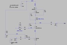
Updated schematic below using the STQ1NK60ZR-AP part. Tonight, I received the STQ1NK80ZR-AP part from Digikey. This 800V part is just as good as the 600 V part. You can literally turn it up until you cannot hear the person next to you and still not feel like it is loud. It is just so clean and sweet sounding. Sometimes, some parts, especially tubes, and to some extent, the VFETS, make things tolerable by sweetening it up and that's the key to their good sound. Not with these parts. They present the truth, no sweetening, but also preserve the excitement. The best DHTs do this. Really enjoying the sound.
Note the following changes:
1. Schade feedback resistors updated to higher values. Ratio is about the same, but you could also try an 18k instead of the 10k, raising the feedback closer to 20%.
2. Middle FET pot changed to 100k, 25 turn, instead of 10k. Provides much wider range to experiment with various devices.
Voltages and current readings on schematic are spot on compared to the real world measurements.
Attachments
So this preamp swings 55V at its output? That’s quite a bit of gain… 4-5V would do for me for now, ideally adjustable though.Voltages and current readings on schematic are spot on compared to the real world measurements.
No, that is just the DC operating point. Sorry if that wasn’t clear. You would turn the 100k pot to get to that value. For 4-5V out, you would need less than 1V in, probably much less.
For the gain, there is quite a lot. I will measure and report back.
For the gain, there is quite a lot. I will measure and report back.
Last edited:
- Home
- Amplifiers
- Pass Labs
- Schade Common Gate (SCG) Preamp