Ninjaed by myleftear while typing but..
You measure the first secondary, while the other secondary is shorted. Then you move the Quasimodo to the other secondary, while the first is shorted.
The documentation shows how to measure the different configurations of a transformer. How you measure it depends on how you intend to use it, ie. if you intend to parallel two secondary's in your product, then do your measurement with the secondary's in parrallel.
Or if you intend to use two secondary's in a center tap configuration, then you first measure between the top winding and center tap, while the bottom winding is shorted to the center tap, then you measure between the bottom winding and center tap, while the top winding is shorted to the center tap. (see image)
And so on for the other configs.
Remember to short the primary, and keep leads short. Long leads or not shorting a secondary or primary does affect the result somewhat.
And if I have a transformer in a configuration of 4 secondary windings with one common terminal. 32-25-0-25-31
And the transformer will first be used for an amplifier 25-0-25, respectively 32-0-32 will not be used at all, then vice versa for another amplifier with a power supply of 32-0-32. How then to proceed, when using a transformer, free windings will be in the air, but when Quasimodo is reconciled, it will still short-circuit all windings that are not for measurement? It's just that the result with the windings shorted and not shorted strongly affects what the oscilloscope shows. And if I measure with closed and during operation some of the windings will be open, is this correct?
Sorry, there is an error in the photo, 5 the center is not short-circuited to the rest of the non-measurable windings
When a pair of crimps is not connected, which will not be used during the operation of the transformer, the ringing is clearly less.
Attachments
Last edited:
The snubber values are measured with Quasimodo across the winding used in the amp's power supply. If the amp is set up for 25-0-25 then measure those windings and use snubber values determined for those windings. If you have a different amp configuration that uses the 32-0-32 windings then you need to measure snubbers for those windings and apply the snubber values for that particular amp configuration. The snubber values may well be different between the two amp configurations, and so you need to use snubber values applicable to the amp configuration being constructed.
If you were keen you could initially measure the snubber values with all other windings shorted. Then apply that snubber to that winding to then measure the snubber values for the other part of the secondary winding. Then with those snubber values applied you could return to measure the snubber values for the first winding section to see if any tweaking of snubber values is worthwhile. That procedure loads each secondary winding as would occur in the amp (rather than the simpler process of shorting the winding).
If you were keen you could initially measure the snubber values with all other windings shorted. Then apply that snubber to that winding to then measure the snubber values for the other part of the secondary winding. Then with those snubber values applied you could return to measure the snubber values for the first winding section to see if any tweaking of snubber values is worthwhile. That procedure loads each secondary winding as would occur in the amp (rather than the simpler process of shorting the winding).
Thank you all for the tips, I also want to ask. If there are no resistors of the required rating at hand, is it permissible to use ordinary variable resistors such as 3296 or similar? It seems that the currents in the filter are minimal.
I wouldn’t hesitate.
Make sure value (wattage / resistance) are good, avoid overpriced exotics.
Make sure value (wattage / resistance) are good, avoid overpriced exotics.
Is there an alternative to the NTD4906 available at Mouser? Thanks!
Is the Infinion AUIRFU8401 suitable?
Is the Infinion AUIRFU8401 suitable?
Last edited:
The original BOM lists IRLB8748 as the substitute, and the part is in stock at Mouser.Is there an alternative to the NTD4906 available at Mouser? Thanks!
I offer full kits with NTD4906.
Thanks Mark for a really fun project! Quasimodo v4 offered a great excuse for me to learn how to put my O-scope to good use.
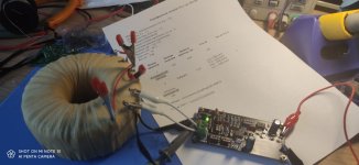
Using Cx= 0.01uF and Cs= 0.15uF, my first victim was an Antek AS-0532 for which I came up with Rs= 71.4 ohms. I didn‘t find that transformer on the measurement only thread, so I’ll post my result there unless someone here disagrees with my finding. My pictures are of this measurement. Next up was an Avel Y236102 with an Rs= 55.3 ohms. I have many more projects I would like to add snubbers to, so I’m not done yet!
I ordered my v4 boards from Oshpark, and as you can see in the picts, they’re really nice. They sent three, so I used one, gave one to a friend, and am offering my last one here for free to the first person in the Continental US to post that they want it. That way everyone can see that someone has claimed it and I don’t end up with more PMs than I can answer. 😎
Attachments

Hi glenv6, I'll be happy to take the last board off your hands. I can reimburse your costs or make a contribution to a cause of your choice. Thanks!Thanks Mark for a really fun project! Quasimodo v4 offered a great excuse for me to learn how to put my O-scope to good use.
Using Cx= 0.01uF and Cs= 0.15uF, my first victim was an Antek AS-0532 for which I came up with Rs= 71.4 ohms. I didn‘t find that transformer on the measurement only thread, so I’ll post my result there unless someone here disagrees with my finding. My pictures are of this measurement. Next up was an Avel Y236102 with an Rs= 55.3 ohms. I have many more projects I would like to add snubbers to, so I’m not done yet!
I ordered my v4 boards from Oshpark, and as you can see in the picts, they’re really nice. They sent three, so I used one, gave one to a friend, and am offering my last one here for free to the first person in the Continental US to post that they want it. That way everyone can see that someone has claimed it and I don’t end up with more PMs than I can answer. 😎

Hi Flashgo - I just sent a PM…Hi glenv6, I'll be happy to take the last board off your hands. I can reimburse your costs or make a contribution to a cause of your choice. Thanks!
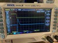
Awesome, thank you Mark! 🍻Congratulations @glenv6 on a very clean build!! Your scope photo shows optimum zeta=1.0 damping. Well done.
Mark,
Question on wiring for 120V primaries in series for 240V applications.
I have always used my quasimodo to test for 120VAC service. So I short all primaries together (2 pairs of primaries to be used in parallel, all shorted).
For 240V applications is the wiring for Quasimodo testing as follows?

Question on wiring for 120V primaries in series for 240V applications.
I have always used my quasimodo to test for 120VAC service. So I short all primaries together (2 pairs of primaries to be used in parallel, all shorted).
For 240V applications is the wiring for Quasimodo testing as follows?
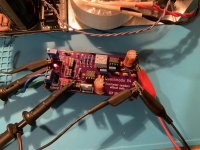
Another Quasimodo is born! When I first read this thread my reaction was cool idea but I need to find someone with a built board to sell. Well I got over that, ordered my own boards, and successfully built a function Quasimodo. Build wasn't that bad at, neither was sourcing the parts despite shortages. As with all projects for noobs I managed to the jumper headers and ended using the 1x1 sockets with leftover resistor leads to hook everything up. Powered it by 2 9V in series. I had ordered 4 transformers from Toroid Corp in Maryland that showed up last week. I promptly set down and was able to measure all 4 in a very short period of time the night I built the board. I was rereading Mark's original article that night and caught the set up for a 2 channel scope and tested again the next day. After some minor struggles being new to using an oscilloscope I got it set up in 2 channel mode. Results where the same but as Mark said the traces are far more stable. The 4 transformers ended up with a resistance of 9-11 ohm on all 8 secondaries tested. It truly amazes me that despite my fears how straight forward this was with all the support provided here, especially since earlier that day I had released smoke from my ACA mini.
One question for Mark, in the 2 channel scope set up you mention using pins to the left and right of C2 for the scope measurements. Any reason you could not just hook up to the 2 leads of C2 instead? I tried it both ways and seemed to work.

1 channel initial tests

After I figured out 2 channel setup, no change in values.

One question for Mark, in the 2 channel scope set up you mention using pins to the left and right of C2 for the scope measurements. Any reason you could not just hook up to the 2 leads of C2 instead? I tried it both ways and seemed to work.
1 channel initial tests
After I figured out 2 channel setup, no change in values.
Congratulations, well done! It takes bravery to place your very first order for PCBs, good on ya. Connect the scope probes however you wish, as long as you get the stable display you seek.
Wouldn’t have happened without your repeated encouragement on this website. Out of curiosity, the traces I got with just using one channel versus two channel do look slightly different. But the two pictures I showed they’re measuring the same resistance level for adequate snubbing. Is the two channel view just a more accurate view of what’s really going on?
Triggering on a waveform with very high dV/dt reduces uncertainty in the trigger timing, so you get a more stable and less schmeeered trace.
Oscilloscope noob appreciates the learning opportunity. And I’m glad you added that section to the original article. Pushed to play around with the scope and learn about the scope as well as our friend Quasimodo.
To anyone interested, I did have to order minimum of 5 boards. I have 3 extras I could mail out if you are interested. Made by JLCPCB, standard fare, nothing fancy. May take a week to get them shipped out but PM if interested.
To anyone interested, I did have to order minimum of 5 boards. I have 3 extras I could mail out if you are interested. Made by JLCPCB, standard fare, nothing fancy. May take a week to get them shipped out but PM if interested.
On the triggering discussion: I've successfully "quasimodoed" many transformers by now deriving trigger directly from the negative slope of the measured signal (and not with a second probe like initially done), by just adjusting the trigger level control of my HM 1007 and get a nicely readable display. Instability only happens if I have too less horizontal speed selected or a wrong trigger level setting, automatic triggering is sometimes not working as nicely... Anyway, the second channel probe and external trigger remain unused in my case. So this may be worth a try... 😉🙂
Greetings,
Winfried
Greetings,
Winfried
- Home
- Amplifiers
- Power Supplies
- Simple, no-math transformer snubber using Quasimodo test-jig