That will lower the resonant frequency, but not provide the necessary damping. It's the 'R' in the 'C+RC' that consumes the oscillatory energy.
There will definitely be switch-off spikes on the step-up secondary. But Quasimodo doesn't clamp the spikes (which might be a good thing, worth doing 😉). It only absorbs the energy stored in a transformer's leakage inductance when the rectifiers on its secondary commutate, reducing generated EMI. Your design challenge is a bit different, since your step-up secondary won't get rectified until it passes through another transformer (presumably).
The 0,22 uF capacitor across the secondary will be a substantial additional load on the amp output, even if the step-up ratio is only 2: or 3:1.
Cheers
Many thanks for the great comment. After some testing I abandoned the idea of the step up transformer and probably will be buying a commercial regenerator in the future.
wgh52,
You're welcome!
Or, maybe you'd be super-generous enough to just share the Gerbers ..?
That'd save the massive undertaking of a Group Buy. 😉
Cheers
You're welcome!
Or, maybe you'd be super-generous enough to just share the Gerbers ..?
That'd save the massive undertaking of a Group Buy. 😉
Cheers
Last edited:
Hello friends! Good afternoon. I wanted to ask if someone has some spare PCBs for the original design that would be willing to sell to me? (shipment would be to continental US).
I'd prefer the through-hole version, but SMD would be OK as well.
If not, I'll order some PCBs, but wanted to prevent having multiple PCBs of something I really only need one of 🙂
Thanks in advance,
Rafa.
I'd prefer the through-hole version, but SMD would be OK as well.
If not, I'll order some PCBs, but wanted to prevent having multiple PCBs of something I really only need one of 🙂
Thanks in advance,
Rafa.
Back in 2013 I sent the Quasimodo V.3 (SMD) and V.4 (thru-hole) Gerbers to OSH Park for fabrication. Their minimum quantity was small and their shipping charge {free} was also small. Maybe if you visited their website today, you'd be able to estimate the cost of fabbing 1 board + undesired spares, today.
Hello friends! Good afternoon. I wanted to ask if someone has some spare PCBs for the original design that would be willing to sell to me? (shipment would be to continental US).
I'd prefer the through-hole version, but SMD would be OK as well.
If not, I'll order some PCBs, but wanted to prevent having multiple PCBs of something I really only need one of 🙂
Thanks in advance,
Rafa.
Hello Rafa
I have 5 spare V4 through-hole boards left with each board R1/D3/R2/R3/R4/R5/P7/C1/C4 installed. Made-costs price only: €5 (one board) + shipping. But I am located in The Netherlands, so shipping might kill it for you.
I used the Infineon AUIRFU8401 successfully as a sub for the NTD4906, but I have non left in stock.
Oscar
Last edited:
I made my own board and it's working as expected, I believe, as I've confirmed a measurement on a specific model and configuration done by merlin el mago in the results thread. I wished more of the measurements would mention configuration, ie. series/parallel/center tapped, but that may be because I'm new to this snubbing.
There's a few things I'd like to clear up, which I may figure out on my own while playing around with it a little more. Otherwise I'll ask here. Answers may be in the thread but it's a lot of pages to go through.
Thanks for your excellent work, Mark!
There's a few things I'd like to clear up, which I may figure out on my own while playing around with it a little more. Otherwise I'll ask here. Answers may be in the thread but it's a lot of pages to go through.
Thanks for your excellent work, Mark!
Attachments

I‘m pretty sure the measurements without specification of a configuration were made in the basic configuration, like 1 secondary shorted and the 2nd connected?
But of course this is a guess into the dark…
But of course this is a guess into the dark…
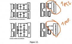
Hello everyone, finally I also put together a wonderful device Quasiomodo, Mark thank you for your work. Everything is super and it works, but in my main transformers with two secondary windings, independent and with a common central wire.
I read the documentation and do not understand, it is stated that for such transformers, 2 pieces of Quasiomdo are needed, but the pictures indicate that the secondary windings that are not measured are short-circuited, either to each other or to the center wire.
Although the text indicates that you need to connect 2 pcs. quasimodo, but at the same time short-circuiting, I do not quite understand. I ask you to prompt and excuse the curve of the test. I am writing through a translator.
Attachments
Last edited:
Hi traktoris
Welcome in the club of us happy campers pampered with marks genius little jigs!
Text says that you need two snubbers, not two quasimodos 😉
You don’t need two quasimodos, you have to short all secondaries not being measured.
So, you connect the first sec and short the second, then you swap, short the first and connect the second. Etc.
(Not sure if connecting the second secondary even would alter the result?)
One (C + RC) snubber circuit for secondary wire-pair A, and one (C + RC) snubber circuit for secondary wire-pair B.
A total of two (C + RC) snubber circuits.
Only one Quasimodo tester PCB is required. First connect it to secondary wire-pair A, and short together ALL OTHER TRANSFORMER WIRES (including all primary wires and all secondary wires). Perform Quasimodo testing and find the optimum R value for secondary wire-pair A.
Now disconnect Quasimodo from secondary wire-pair A.
Connect Quasimodo to secondary wire-pair B, and short together ALL OTHER TRANSFORMER WIRES (including all primary wires and all secondary wires). Perform Quasimodo testing and find the optimum R value for secondary wire-pair B.
Success! Two snubber circuits, one Quasimodo tester PCB. Exactly as member @myleftear has explained.
_
Last edited:
Ninjaed by myleftear while typing but..
You measure the first secondary, while the other secondary is shorted. Then you move the Quasimodo to the other secondary, while the first is shorted.
The documentation shows how to measure the different configurations of a transformer. How you measure it depends on how you intend to use it, ie. if you intend to parallel two secondary's in your product, then do your measurement with the secondary's in parrallel.
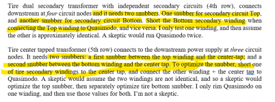
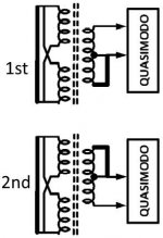
Or if you intend to use two secondary's in a center tap configuration, then you first measure between the top winding and center tap, while the bottom winding is shorted to the center tap, then you measure between the bottom winding and center tap, while the top winding is shorted to the center tap. (see image)
And so on for the other configs.
Remember to short the primary, and keep leads short. Long leads or not shorting a secondary or primary does affect the result somewhat.
You measure the first secondary, while the other secondary is shorted. Then you move the Quasimodo to the other secondary, while the first is shorted.
The documentation shows how to measure the different configurations of a transformer. How you measure it depends on how you intend to use it, ie. if you intend to parallel two secondary's in your product, then do your measurement with the secondary's in parrallel.
Or if you intend to use two secondary's in a center tap configuration, then you first measure between the top winding and center tap, while the bottom winding is shorted to the center tap, then you measure between the bottom winding and center tap, while the top winding is shorted to the center tap. (see image)
And so on for the other configs.
Remember to short the primary, and keep leads short. Long leads or not shorting a secondary or primary does affect the result somewhat.
Attachments

Thank you all for your answers, everything is clear. So there is something to sell now)).
Another question is whether there can be a C-RC tuned with the help of Quasimodo, which will stand after the transformer for lowering from 220V to 100V, for example, to power equipment for the Japanese market. Or will C-RC just in front of the diode bridge be critical?
Another question is whether there can be a C-RC tuned with the help of Quasimodo, which will stand after the transformer for lowering from 220V to 100V, for example, to power equipment for the Japanese market. Or will C-RC just in front of the diode bridge be critical?
Last edited:
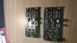
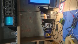
Besides the perfect how-to measure instructions above... here's an actual application of part of fig.13. in situ.
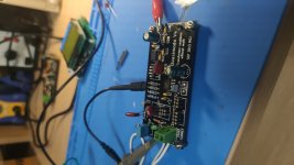
What is the stabilizer in the photo, if not a secret?
Not sure what you mean by stabilizer? I just worked with the legs of the caps and leads from the resistor etc. making the connections. Little bit of glue between the caps. No secret. I looked for a more clear image... I didn't take on at the time. Just followed MJ's drawing in fig.13. Bent the leads at the bottom after everything was soldered up to slot into the connectors....
darn that's beautiful, farrell!
(as always actually 😀)
My phonyphone and my inadvertedness bungled your screenname, apologies!
What is the stabilizer in the photo, if not a secret?
I always thought this was from pfarrell but now I‘m not sure anymore. Anyway this illustrates quite well what’s in the bag!

- Home
- Amplifiers
- Power Supplies
- Simple, no-math transformer snubber using Quasimodo test-jig