I'm wrong here. These parts are in the BOM.Lookin at the values I may need, 150r/392r/30k I can come close, not exact.
Edit; looks like a road trip is in order. I only have 30k resistors. I'll pick up a few more items while I'm there.
Those numbers I see in the pic look about like my 20v donut aleph 30 mono. Figure 2.2 ish amps per rail. I have to think the sheet is right. I’m looking on my phone, so I can’t look at the zip to see the calcs@rhthatcher Randy in the Aleph30 stereo build notes you state "the 4U Deluxe Case is a perfect candidate".
Did you refer to the 4U 300 Case? Are two heatsinks with 0,31 K/W enough for an Aleph 30 Stereo build? After reading other statements like from @Zen Mod I would go for a 5U 400 Case (will get me in trouble with my gf..)
I am all new to the Aleph topology. What is the total bias current for one channel when i build my Aleph as proposed in the Aleph30 build notes?
Can I use the "Aleph Power calculation" spreadsheet created by @wuffwaff for this project to do thermal calculations for certain bias points?
You can dial bias up or down using heatsink temp as a guide. How about 4u/400 or 500 if you want to crank up bias?
Looks like that was in reply to my question re: if you had LOAD resistors. Sorry if I was not clear.I do have a box or resistors, but I haven't checked what values they are. I won't order anything from amazon but there's an electronics store 1-1/2 hrs away.
I see you left out R29, R33 is this because you left out Q7?
I'm leaving out Q9 = R31 & R35. OK?
If you leave out Q9 - leave out R31 & 39
If you leave out Q13 - leave out R35 & 43
For Aleph 30:
I don't see that anyone else has answered you... You said you wanted to learn. Site the schematic... site the build document. Tell us how you interpret them and where there is a lack of clarity. Why did you choose Q9? If you explain your reasoning, I'll help. Another person may just tell you the answer.I see you left out R29, R33 is this because you left out Q7?
I'm leaving out Q9 = R31 & R35. OK?
You have a great example in Randy's build. Heck, you even entered to win his boards when you have your own boards and parts already. Why not emulate his if you're unsure? You asked a lot of great questions when you were sorting out the errors in your Aleph J build. Love that you're doing it here too. Reading smoke signals is too hard. 😀
Edited to add - Well heck... clearly I type too much. Randy already answered.
I don't have a particular reason for leaving Q9. I just figured that spot is on the expansion end of the board that I won't use. May as well fill middle R35 & R43 is empty as is Q13.I don't see that anyone else has answered you... You said you wanted to learn. Site the schematic... site the build document. Tell us how you interpret them and where there is a lack of clarity. Why did you choose Q9? If you explain your reasoning, I'll help. Another person may just tell you the answer.
You have a great example in Randy's build. Heck, you even entered to win his boards when you have your own boards and parts already. Why not emulate his if you're unsure? You asked a lot of great questions when you were sorting out the errors in your Aleph J build. Love that you're doing it here too. Reading smoke signals is too hard. 😀
Edited to add - Well heck... clearly I type too much. Randy already answered.
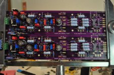
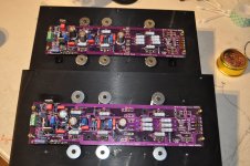
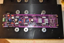
Looking good!!! Thanks for sharing your picture!PCB populated. I have some ceramic insulators about 2mm thick. can I use them under the MOSFET's?
I trust you got the right resistors and pot settings.
A few comments/questions:
Flow some more solder on top around the resistors and QD spades.
Are you going to use QD spades for your speaker outs?
are you going SE only in? Looks like it with the jumper wire installed.
Use a little thermal goop with your mica and you'll be good to go.
Thanks. I've got thermal goop.
SE like everything else here. We have 7-8 amps floating around.
Should I not use QD spades for speaker-outs?
I'll have this up and running in no time. Maybe this evening.
SE like everything else here. We have 7-8 amps floating around.
Should I not use QD spades for speaker-outs?
I'll have this up and running in no time. Maybe this evening.
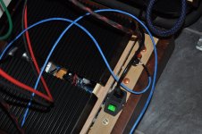
Together ready to run.
Bias set to .008mv. I'm not sure if it should be .0001 or 5''Added up resistor values after the math and I come up with 2.5A. Not positive which trim-pot adjust's this
Let it run on the bench and no smoke. Tomorrow I'll see if it makes music.
The boards readily take solder. Whoever made them's a Class Act.

Congratulations!!! Well done building so fast and getting it fired up on the first try!I couldn't help myself. We have music. 😗
It's the first build I've done that worked at first plug in. Tomorrows going to be a sit and listen day. Tonight, I'm going to see how hot the heatsinks get at idle.
I’m looking forward to pix and listening impressions!
That measurement is across what resistor(s)?Together ready to run.
Bias set to .008mv. I'm not sure if it should be .0001 or 5''Added up resistor values after the math and I come up with 2.5A.
I know I poke at you, but what's not clear in the build docs / schematic / labeling on the board? 😀 Ask if you're unsure. You have it working. No smoke!Not positive which trim-pot adjust's this
Awesome! Nothing feels better than things working the first time. I think you also have the honor of first one built other than Randy's. So cool.I couldn't help myself. We have music. 😗
It's the first build I've done that worked at first plug in. Tomorrows going to be a sit and listen day. Tonight, I'm going to see how hot the heatsinks get at idle.
Those measurements were made across the big 3w source resistors. Measure say 400mv divide by .47= .85 X 3 comes up with 2.5
DC off-set trim pot R14
AC gain R21
I don't know what DC off-set should be set too. It's at .008mV now.
Heatsinks hot spot is 57°C. Manual says the thermal shutdown is 70°C
It sounds very good. Seems to have more balls than the J. A bigger chesty sound. It's been running with music playing 1/2 hr so far. I should do some tractor work today but I'm not. Music all day. Thats the best thing about being retired. When you wake up you have choices.
Thanks.
I miss the LED's.
Attachments
Giving you some fun grief just because I'm jealous. I know it was late when you posted and that you had it correct (otherwise you would not have had music).
See your first post re: "bias" voltage. Then see your second... then note your DC offset vs. the measurement you noted for your bias in #91. 😀
Seriously, I poke for fun. If I saw anything of concern, I'd be more direct.
Congrats again!
See your first post re: "bias" voltage. Then see your second... then note your DC offset vs. the measurement you noted for your bias in #91. 😀
Seriously, I poke for fun. If I saw anything of concern, I'd be more direct.
Congrats again!
Those measurements were made across the big 3w source resistors. Measure say 400mv divide by .47= .85 X 3 comes up with 2.5
I don't know what DC off-set should be set too. It's at .008mV now.
Heatsinks hot spot is 57°C. Manual says the thermal shutdown is 70°C
2.5A Bias - little hot, but some say to run bias high for best sound. If your heatsinks hit temp equilibrium and aren't too hot, leave it as-is.
Can you put your hand on the heatsink for 5 seconds? If so, you're good. Try running the heatsinks in a vertical orientation to see how that works, too.
DC Offset target is <100mV
If you're at 8mV or .008V, that's great!
It sounds very good. Seems to have more balls than the J. A bigger chesty sound. It's been running with music playing 1/2 hr so far. I should do some tractor work today but I'm not. Music all day. Thats the best thing about being retired. When you wake up you have choices.
What you're hearing is the reason that drove me to do this project. It started with the rebuild of an Aleph 5 on old PCBs. The classic Aleph sound mesmerized me and stuck with me well after I shipped the amps back to their owner. Later I compared notes with @wg45 on his Aleph 2 build and my Aleph 30 and the word that came to mind is "authoritative".
Enjoy the music & congrats again on your successful build!

The hottest part of the heatsinks is right over the PS. The rest, around 45°C. Measured with an infrared thermometer.
Post #91, my nomenclature is wrong. I said bias where it should have been DC offset. I tend to act before I think. Something I learned at a very young age riding motorcycles.Giving you some fun grief just because I'm jealous. I know it was late when you posted and that you had it correct (otherwise you would not have had music).
See your first post re: "bias" voltage. Then see your second... then note your DC offset vs. the measurement you noted for your bias in #91. 😀
Seriously, I poke for fun. If I saw anything of concern, I'd be more direct.
Congrats again!
- Home
- Amplifiers
- Pass Labs
- Classic Aleph Amplifier for Modern UMS Chassis Builder's Thread