Yeah, my momentum stalled a bit while building a HV shunt psu. Had to order caps with correct voltage ratings, should be listening in stereo by the end of the week. In the meantime I'm enjoying your journey 🙂

All good... just waiting to hear your impression!
DEFiSIT uses a real SIT though, right? We're kind of running out of those...one of best versions is already made .......
it's called DEFiSIT ....... then all of its derivatives
of course, not saying that field is exhausted ...... 🙂

just an example, post #119
https://www.diyaudio.com/community/...2-sit-babelfish-xa252-set.373443/post-6695282
https://www.diyaudio.com/community/...2-sit-babelfish-xa252-set.373443/post-6695282
Nice! I had not seen that before. Will read more on that thread. Thanks for sharing.just an example, post #119
https://www.diyaudio.com/community/...2-sit-babelfish-xa252-set.373443/post-6695282
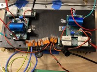
I’ve got SCG pre in plank amp form playing in stereo. (110VDC and 55mA)
I’m using a Gustard dac as volume control and the SCG is driving an M2 clone. This combo sounds very good. The preamp sounds a bit better after about 45 mins, when the psu heatsink reaches its operating temperature the voltage stabilizes.
This version is based on your original resistor loaded schematic with RL =1K.
Ra7,
If your changes are further improving/refining the sound your hearing, this pre will be a must have.
Nice one!
Attachments


If I was to think about building something like a FETSET I would first play around in LTspice. If I was to do that, I might find that a circuit similar to the one shown in post #2 runs out of voltage headroom when asked to do something like put 20 watts into a 1500 ohm OPT. A little tinkering might discover that the p-fet is starved for voltage, so adding a 10 volt Zener in series with the bottom feedback resistor will give it more headroom. If I was to play around a bit further in LT spice I might be able to simulate a complete two stage FETSET amp. Since I will be sitting around in a doctor's office twice in the next two days for some minor surgery, I might be tempted to play a bit more in the simulator.I can envision a complete UNSET amp design with no tubes. There are some serious SiC fets rated for 700 volts available today for about the same price as a big tube ($20). I doubt that I will ever build it due to the flak that it would draw.
If someone was thinking about breadboarding a circuit like this without spending much money they would look into their parts collection and find two sets of suitable OPT's. One might be a good set of 1500 ohm OPT's that would need over 300 volts of B+ to get 20+ watts of audio. That rules out the 500 to 600 volt fets on SOA concerns. Suitable budget 1000 volt fets are not in stock anywhere. It might be possible to parallel two of the IXYS IXTP3N100D2 that I have to get into the safe zone. There is a pair of 600 ohm cheap Chinese OPTs with dubious quality that might work with some 500 volt depletion fets that I have.
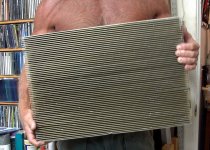
Getting 20+ watts output with either option would burn 60 to 70 watts from two stages requiring a pretty big heat sink for a single channel amp. Unfortunately, I sold the monster heat sink that I was saving for a big amp when I had to move everything I own 1200 miles on 3 weeks notice. I will need to find something.
Attachments
Awesome ideas! Love the name FETSET!
One question: why do you need an OPT at all? Here in Pass Labs land, we routinely run 1-2 amps of bias current at lower voltages. Couldn’t that work?
You could also throw a follower on the triode gain stage, similar to something Mike R. presented at Burning Amp:

I am also toying with this idea of a SCG gain stage followed by a follower. The gain stage is easily swinging 25V and so all you need after it is current gain for the loudspeaker.
Wish you a speedy recovery! Would love to see you build this monster.
P.S.: if you need heat sinks, just ask
One question: why do you need an OPT at all? Here in Pass Labs land, we routinely run 1-2 amps of bias current at lower voltages. Couldn’t that work?
You could also throw a follower on the triode gain stage, similar to something Mike R. presented at Burning Amp:
I am also toying with this idea of a SCG gain stage followed by a follower. The gain stage is easily swinging 25V and so all you need after it is current gain for the loudspeaker.
Wish you a speedy recovery! Would love to see you build this monster.
P.S.: if you need heat sinks, just ask
I'm sure that a low voltage version that directly feeds a speaker could be made to work. The car radios of the 1960's used a single ended fat germanium transistor in class A driven by low voltage tubes to drive a speaker. There was usually a choke or 1:1 OPT to keep DC out of the speaker. Some even used a step up OPT to get more power from a 12 volt car battery. I played with that stuff as a kid. Hey, germanium is coming back in style today.Awesome ideas! Love the name FETSET!
One question: why do you need an OPT at all? Here in Pass Labs land, we routinely run 1-2 amps of bias current at lower voltages. Couldn’t that work?
You could also throw a follower on the triode gain stage, similar to something Mike R. presented at Burning Amp:
I am also toying with this idea of a SCG gain stage followed by a follower. The gain stage is easily swinging 25V and so all you need after it is current gain for the loudspeaker.
Wish you a speedy recovery! Would love to see you build this monster.
I have a tube amp in the planning stage that runs an UNSET style voltage amp into a cathode follower made with some fat tubes capable of 1.4 amp peak currents. A lower voltage follower with a choke in the cathode circuit should work too. If I hadn't given away the huge 5H @ 5A chokes that I had, I would have built that already. The cathode / source follower concept allows for modulating the plate / drain voltage to reduce the average dissipation in a class A follower to reduce the size of the heat sink.
Looking forward to the tube follower design, George! What would be really unique is an FET gain stage and a tube follower... now that would be cool!
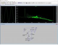
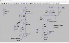
Here's an updated schematic with a couple of tweaks:
1. Revised biasing for the gain FET. The pot is bypassed with a cap to ensure that the 1k resistor is at ground for AC frequencies. Any ordinary electrolytic will do fine. I am using the Nichicon MUSE variety. Silmic and others are great. My impression so far is that this cap doesn't contribute too much to the sound.
2. Added a cap to the input and a bias circuit to put about 10 V on the gate of the bottom FET. This takes the bottom FET off the low end of the capacitance curves and into the region where the inter-pin FET capacitances are lower and more stable. It could be operated without the input cap and the bias circuitry, as in the original post.
The schematic below uses the larger Fairchild FETs. In my testing with other FETs, there is a definite difference in sound. In other iterations, we might be able to get away without heatsinks, operating in the 10 mA region. Of course with 55 mA, this has a powerful sound.
Thanks for the updates ra7, I will add these changes to my SCG plank preamp soon.
After listening with smaller mosfets, did you feel the FQA's and higher bias current were overall a better sound?
After listening with smaller mosfets, did you feel the FQA's and higher bias current were overall a better sound?
Hi Vunce! Yes, those changes, especially getting the bottom FET's gate off the ground will be a significant improvement.
Honestly, I've only tried the Fairchild version and another one with VP0106 on the bottom and STQ1N60 on the top. That one operates at similar voltages, but at 10 mA through the FETs. This other version does have a different sound. While the FQP version sounds powerful and at ease, the other version sounds more natural at the top end (it is not lacking in power but it doesn't make that its main attribute). I want to try even more FETs, especially some others that have real pentode-like curves. For example, this one:
https://www.vishay.com/docs/91500/sihf10n40d.pdf
Another thing I'm hearing is that those feedback resistors impart some sound of their own. It is very marginal but it is there. So far, I've tried no name metal film ones I bought from eBay more than 10 years ago, RN65 Vishay, and Kiwame. The no name ones impart a very slight edge to the high frequencies, whereas that edge is gone in the RN65. And the Kiwames sound the best, most natural. This might all be a figment of my imagination , but I "think" I hear the difference.
Honestly, I've only tried the Fairchild version and another one with VP0106 on the bottom and STQ1N60 on the top. That one operates at similar voltages, but at 10 mA through the FETs. This other version does have a different sound. While the FQP version sounds powerful and at ease, the other version sounds more natural at the top end (it is not lacking in power but it doesn't make that its main attribute). I want to try even more FETs, especially some others that have real pentode-like curves. For example, this one:
https://www.vishay.com/docs/91500/sihf10n40d.pdf
Another thing I'm hearing is that those feedback resistors impart some sound of their own. It is very marginal but it is there. So far, I've tried no name metal film ones I bought from eBay more than 10 years ago, RN65 Vishay, and Kiwame. The no name ones impart a very slight edge to the high frequencies, whereas that edge is gone in the RN65. And the Kiwames sound the best, most natural. This might all be a figment of my imagination
, but I "think" I hear the difference.Vunce, all,
I just listened to the above schematic last night but with the gate of the bottom FET at about 20 V, putting the source of the bottom FET at 24 V (20V + the Vgs). This was a trial to put the bottom FQP part in the same Vds range as the BA-3 pre. It sounds very nice, and I'd say better than with less volts on the gate. After all, if Papa figured this was a good range in which to operate the part, then it must be good, right? I think this is close to the final variation and I am happy with the sound. It ticks all my boxes and makes no apologies. It sounds natural, relaxed, and powerful. Of course, the negative phase H2 and imaging is there. Very much comparable to the 10Y pre.
The way to get about 20 V is to put another 10k resistor between RV2 and ground. If you've already built it or planning to build, I'd shoot for 20V on the gate of the bottom FET.
I've got a juicy update for later today. Just need to put all the information together.
of course, if one wants to retain DC coupled gate to input, you can always introduce negative rail, to have P channel mosfet having some voltage to breathe ( and keep capacitances, whatever small they are, on bay)
Yup, ZM, you had suggested it and it is on my list of things to try. I have built a negative reg as well. But, I like this solution too… with just a few resistors and pots and one supply you can get the same result. I am not too bothered by the input cap.😲


- Home
- Amplifiers
- Pass Labs
- Schade Common Gate (SCG) Preamp