Ah, I see. So, instead of 47k after the cap, put something lower. How does this impact the output impedance?you can always combine good thing of having CCS up (ease of setting, possible lower rail) , and defining real load with shunting resistor after output cap
Pa did those things in Yore, when he was still messing with preamps (later he decided that younger one must deal with that preamp PITA, while he's dealing with kosher things)
and, of course, those things were done from dawn of electronics
if I tel you , I'll ned to kill you ........ 
simple - you just need to learn to construct basic circuit elements using U/I graphs of part, where you draw load lines etc. , exactly as in Yore when ppl are actually seeng pulsating currents in glass envelopes
load (for common cathode connected triode) is in anode
above anode is usually positive rail
if that anode load is resistor, there is usually series cap, routing AC signal further
now - load is load - it is impedance with which anode is "burdened" and anode really doesn't care to where other point of load is connected - it just care what effective burden is
so - primary load (CCS) is huge and connected to anode, also having important role of delivering juice to anode
now - you solved Iq with CCS
what if you want lower AC load, without ruining nice setting of Iq?
oh, how I wish to have nice resistor , Kiwame please, it's so better looking than two lousy sand parts ......
eurEka, I can put cap in series to Kiwame, why not AudioNote cap or even better Duelund one (you can use it also as top lid of preamp, how big and beautiful it is)
som now you have CCS to do some good, and you have Kiwame+Duelund in parallel to CCS
problem solved
now - I need another Duelund as output cap, then another Kiwame to shunt that Duelund ( when I pull fancy interconnect out, something must keep output node of Duelund down, preventing bloody preamp of killing my SIT amp next time I connect them together
ups, problem - now I don't have a room in my room , to have two Duelunds and two Kiwames
besides , DUelund is big enough so I can use it as bottom lid ( ceiling, I'll move it few feet anyway, need room), BUT!!! hiding Duelund beneath is Blasphemy, so I can't do that
let kill one Duelund and one Kiwame, actually getting some space to put my a$$ in room and listen to beautiful Kiwame and Duelund Sounds, my divinity of them is so big so having just one of each is enough for my sense of purpose
aha - wait - stupid anode doesn't know when first Kiwame is connected - everything where it can be connected - as long is fixed and calm , can be called "virtual GND" ........ so why not using real GND - it's certainly most fixed and calm level in entire preamp
so - just move first Kiwame to output (as shunt to GND) , size output Duelund to cover for entire Freq. area you want it to cover, so you're free (I'm free, we're free - I'm lost in roles here already - who when why)
you have space for A$$, I can shoot neighbors with Kiwame and Duelund at least once , we have all nicety nice THD skyhigh 2nd neg can give us ......... and we are all happy
damn

Yeah yeah… it’s frequency-dependent voltage dividers all the way…
I like Dueland as preamp top idea… it doesn’t even have to be part of the circuit
I like Dueland as preamp top idea… it doesn’t even have to be part of the circuit
it isn't divider, it is dominant load
same as parafeed with toobz - you have one big impedance load at DC side of things and another (how big, by choice) on AC side of things
btw - you can squeeze it cheap - Duelund as jewelry, no function - just mock-up your own clone with no innards ........ that should be easy
same as parafeed with toobz - you have one big impedance load at DC side of things and another (how big, by choice) on AC side of things
btw - you can squeeze it cheap - Duelund as jewelry, no function - just mock-up your own clone with no innards ........ that should be easy
what is the gain of this preamp?
I suppose output impedance is quite high?
Gain is 9 or about 19 db. This is with a 1k load. Others were about the same.
I have not measured or calculated the output impedance yet, but working into a 10k load of the ADC, the output is down -3db at 50k+. So, no problem there.
Hi cody! Yes, I am using the HV Salas shunt reg. The supply voltage to input of shunt reg is about 140 V, output of shunt reg is about 100-120 V. It was built around the LuminAria.This one looks really fun - well done! I Like ZMs idea of having a shunt resistor after the CCS. That could be a killer combo.
on another note, are you using the HV Salas shunt, or does the Ultrabib support those kind of supply voltages?
okay, I get it. You are loading down the gain device with the resistor after the cap, thereby turning the loadline clockwise.... making it the AC "working" loadline. I'll play with that. I think Mike mentioned that in the LuminAria thread too but it went over my head at the time 😀it isn't divider, it is dominant load
same as parafeed with toobz - you have one big impedance load at DC side of things and another (how big, by choice) on AC side of things
btw - you can squeeze it cheap - Duelund as jewelry, no function - just mock-up your own clone with no innards ........ that should be easy
That resistor after the cap is in parallel with the gain device and is really a potential divider. In fact, couldn't we say the entire gain chain is a bunch of potential dividers connected together?
well, as they say - with statistic you can confirm anything .......... 
but no - it is not divider
free your brain of habit to anchor load to where it is "usually" anchored
and differentiate DC domain from AC domain
in AC domain , CCS connected between positive rail and drain of upper mosfet is in parallel with resistor shunting your output cap to GND
in AC domain, GND is audio GND ( and you're using it usually to connect apparatus to outer world ) while positive rail is Virtual GND
and , in AC domain, virtual GND and "real" GND are the same, having same function
example = Aleph L ( schm everywhere) - in DC domain, sole active mosfet in gain stage is loaded ( and you can freely say - armed) with CCS in drain
then there is output cap and string of resistors to GND , and that string is used as simple stacked L attenuator ( called Level Control)
in DC domain, drain load for said mosfet are drain CCS in parallel with said resistor string; resistor string having much lower resistance than CCS itself, so dominating
btw. as in many things , ZM is also Master of Own Special Explanations; fun with them - most funny and complex and amusing ones, perfectly serving as Universe of Truth and Rest...... were shattered in first next benign trouble
well, after few decades of practicing , it taught me to take my self less serious, if it didn't made me smarter
so - if you like to call it divider - call it - as long it helps you to bring functional circuit
ZM, I may need a few weeks to digest that... coz I’m slow…
But, I can confirm that it does work. My output cap is small, so I can't quite go down to 1k without sacrificing bottom end but this is a neat trick for playing with the loadline while still enjoying the benefits of the CCS. Thanks!
But, I can confirm that it does work. My output cap is small, so I can't quite go down to 1k without sacrificing bottom end but this is a neat trick for playing with the loadline while still enjoying the benefits of the CCS. Thanks!
Last edited:
Oh, this is really good and so much fun. Another lever to pull.
Here is the CCS loaded version with 10k output resistor. This is great sound. Hmmmm... can I get H2 a little higher without introducing other harmonics?

Here is the CCS loaded version with 10k output resistor. This is great sound. Hmmmm... can I get H2 a little higher without introducing other harmonics?
one more thing, interesting to try - you can include nice small JFet buffer in front of input MOS; quite possible that you'll get more resolution
price - you'll need additional neg rail, which can only improve things for input mos, and - with JFets in front, input capacitances should be even easier to deal with
price - you'll need additional neg rail, which can only improve things for input mos, and - with JFets in front, input capacitances should be even easier to deal with
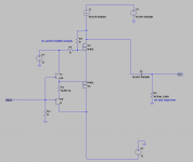
found some time, while finishing morning (noon afternoon) coffee, to make a sketch
edit : few tricks still in the bag, sugar and gain can be altered at least in few ways more, without sacrificing anything in form of dividers
edit : few tricks still in the bag, sugar and gain can be altered at least in few ways more, without sacrificing anything in form of dividers
Attachments
Last edited:
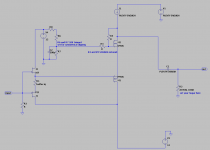
of course, I forgot to draw that trimpot biasing thingie for Schade, was in hurry
will add edited sketch later
edit: added sketch
will add edited sketch later
edit: added sketch
Attachments
Last edited:
Thanks ZM! That’s a neat idea. I kind of like the simplicity of a single supply… makes me feel like it is analogous to the other great triodes and simple designs 😀
There might be some low input capacitance MOSFETS out there. That is one thing I want to try also. So many options…
There might be some low input capacitance MOSFETS out there. That is one thing I want to try also. So many options…
now, you probably know that altering Schade resistor values would vary transfer characteristic and, in same time, both THD Spectra and gain
"real load resistor" should dominantly vary THD Spectra, while not so much gain of stage
TP2640 and TN2640 are nice little mosfets, though you need to take care of not pushing them (TO92) above, say, 250-300mW
"real load resistor" should dominantly vary THD Spectra, while not so much gain of stage
TP2640 and TN2640 are nice little mosfets, though you need to take care of not pushing them (TO92) above, say, 250-300mW
Thanks Indra and ZM! We want to find an alternate only for the bottom source follower, right? Need a P-channel one there. I’ll check out the options listed here. You guys have given a lot of new ideas to explore! Thank you!
- Home
- Amplifiers
- Pass Labs
- Schade Common Gate (SCG) Preamp