Beside cascode, this will increase current trough R24 and R25 and these must be adjusted as well.Hello Tibi,
I am now building a new Q17 again, this time I have reduced R3 from 150 to 100 ohms. This increases the current in the cascode. I have loaded the Space models of the ZVN and ZVP types into the simulation and I got the impression that they play cleaner with a little more current. So just from the simulation evaluation, in reality I have to build it up first.
Tim
Regards,
Tibi
Hello,
I made a drilling plan for the Q17-Mini.
You just have to print it at scale 1 and mark holes.
https://github.com/stefaweb/Q17-a-QUAD405-audiophile-approach/blob/main/Q17-Mini-drilling.pdf
Enjoy!
Let me know if some resistor values need to be changed if ZVP2106A are used instead of BS250P for Q9/Q11.
Stef.
Hello Tibi,Beside cascode, this will increase current trough R24 and R25 and these must be adjusted as well.
Regards,
Tibi
I will install R24+R25 = 12k/1W, which is in my opinion in the green range.
regards Tim
If you keep R3=150ohm, there is no need to change R25 & R25.
Regards,
Tibi
Thanks.
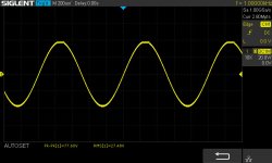
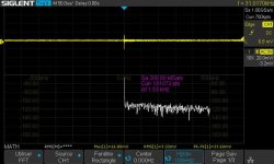
A little too round at 20KHz (IMHO).
Stef.
.
Attachments

This is a nice shape that indicate a low level of odd harmonics. To reach a perfect square wave you need to add odd harmonics.
What I like are even harmonics and the amplifier was designed with this in mind. It was designed for pleasure and joy, not pain.
Regards,
Tibi
What I like are even harmonics and the amplifier was designed with this in mind. It was designed for pleasure and joy, not pain.
Regards,
Tibi
Yes, you are OK at 12K/1W....
I will install R24+R25 = 12k/1W, which is in my opinion in the green range.
...
Regards,
Tibi
Hello Tiby,
I didn't know about the influence of harmonics on the square signal.
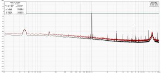
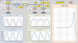
I redid some measurements with REW and the scope. I put the files on the Github repository for those who are interested.
I tortured the amp a bit to see how it behaved with a high signal. No parasitic oscillation, no heating on the PCB tracks, and it clips high enough. With 48V DC and 8R charge, the amplifier clip at 27v for 540mV RMS at the input.
Stef.
.
I didn't know about the influence of harmonics on the square signal.
I redid some measurements with REW and the scope. I put the files on the Github repository for those who are interested.
I tortured the amp a bit to see how it behaved with a high signal. No parasitic oscillation, no heating on the PCB tracks, and it clips high enough. With 48V DC and 8R charge, the amplifier clip at 27v for 540mV RMS at the input.
Stef.
.
Attachments
Hi again,
I gave the diagram of the amplifier in 3 pairs version with all the information that I could glean.
Would it be possible to check it especially for the values of resistances and their wattage?
I also added capacitors at the foot of each of the output MOSFETs. I put 220uF/100nF but I didn't know what the minimum value would be.
Stef.
Attachments
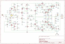
You have a short on the mirror between Q9 and Q11 drains. R29 and R30 must be between 1K and 10K.
Decoupling caps are OK at 220uF, however, larger caps will improve amplifier damping on complex and heavy speakers.
Use a linear power supply with synchronous rectification for good measurements and exceptional sonic performance.
Regrads,
Tibi
Decoupling caps are OK at 220uF, however, larger caps will improve amplifier damping on complex and heavy speakers.
Use a linear power supply with synchronous rectification for good measurements and exceptional sonic performance.
Regrads,
Tibi
Capacitive loading on the high output impedance Q5/Q6 VAS stage becomes significant with three pairs of FETs.
I would consider a follower.
I would consider a follower.
Yes, this is what I did with 6 pairs and reduced Q5&Q6 bias current to 35mA.
Even Q17 will sound very good with only one pair of mosfets, people tend to be not satisfied until they see a D'Agostino monster. But from 2 pairs onward, I think we are a bit out of DIY.
Regards,
Tibi
Even Q17 will sound very good with only one pair of mosfets, people tend to be not satisfied until they see a D'Agostino monster. But from 2 pairs onward, I think we are a bit out of DIY.
Regards,
Tibi
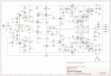
New version.
I changed coupling capacitors for output MOSFET to 100uF (Alex's board use 100uF).
I removed the wrong short on Q9/Q11.
Changed R29 and R30 to 1K (for now).
I've more question:
The goal would be to draw a luxury 3 pairs version (with a compact size, around 75x150 with only 6 holes to drill) if the sound of the one pair pleases me. But if 3 pairs is too difficult, 2 pairs will be nice too.
Stef.
EDIT: what is "D'Agostino monster"?
EDIT 2: I also know how to build good analog power supplies. 😉
I changed coupling capacitors for output MOSFET to 100uF (Alex's board use 100uF).
I removed the wrong short on Q9/Q11.
Changed R29 and R30 to 1K (for now).
I've more question:
- What will be the more accurate voltage for a 3 pairs board (and If you know, for a 2 pairs board)?
- How to have a better management of symmetrical voltage for U1?
- What about C2 (non polar or double +--+ capacitor)?
- How to have for sure the less possible level of offset at output?
- How to calculate the right value for R29/R30?
- What is the dumping factor of a 3 pairs board?
The goal would be to draw a luxury 3 pairs version (with a compact size, around 75x150 with only 6 holes to drill) if the sound of the one pair pleases me. But if 3 pairs is too difficult, 2 pairs will be nice too.
Stef.
EDIT: what is "D'Agostino monster"?
EDIT 2: I also know how to build good analog power supplies. 😉
Attachments

Last edited:
The short on Q9 & Q11 drain's is still there and gate and drain on Q11 must be connected.
Q5 gate must be connected to Q8 drain trough R7.
See my schematic here https://www.diyaudio.com/community/...approach-to-perfect-sound.374507/post-6734020
Tibi
Q5 gate must be connected to Q8 drain trough R7.
See my schematic here https://www.diyaudio.com/community/...approach-to-perfect-sound.374507/post-6734020
- For a 3 pairs I'll go for +/-65V. On two pairs still on +/-50-55V
- As I mentioned, in a previous post, use resistors instead Zenners. Another solution would be to use a schottky in series with zener.
- I would go for C2 double +--+ capacitor
- Opamp with jfet input and good C2 and C7
- R29 and R30, together with C13 and C14 form a low pass RC filter. My calculation was to have a cutoff outside audio band <10Hz. with 1K and 220uF you get ~4.5Hz. This allow smooth amplifier power on and off. No bump in speakers.
- If you have a good power supply, with one pair is good, with three even better. 🙂
Tibi
Thanks Tiby.
I will look at this in detail. 2 pairs finally. I don't build anything above 60V for safety reasons (and caps above 63V are too big and expensive).
I just found out that I made a scoring error for the Q17-Mini. I built it with 10R for R29/R30. I've to update schematic and BOM (and update the prototype).
Stef.
Last edited:
Hi Piersma
MKS or MKP ?
Update done on Github.
I like the idea of the schottky in series with zener and it is easy to try. I prefer a solution without setup (trim).
Stef.
MKS or MKP ?
Update done on Github.
I like the idea of the schottky in series with zener and it is easy to try. I prefer a solution without setup (trim).
Stef.
Preferably a MKP, but a MKS would do also fine !Hi Piersma
MKS or MKP ?
Update done on Github.
I like the idea of the schottky in series with zener and it is easy to try. I prefer a solution without setup (trim).
Stef.
- Home
- Amplifiers
- Solid State
- Q17 - an audiophile approach to perfect sound