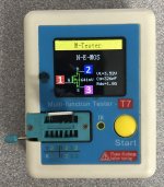
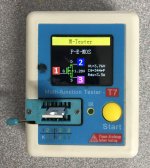
On my Q17 I have 680uV DC offset with C7 1uF Mundorf Evo Silver-Gold and C2 Rubycon Black-Gate NX.Hello Tibi,
I always have 40 mV DC offset, this has always been the same for all my setups.
Regards,
Tibi
2N7000 and BS250P are difficult to get now (same for ZVP).
For the 40mV offset, we may be have to sort the zeners? I've currently 15.10v for positive and 14.75v for negative rail.
Stef.
For the 40mV offset, we may be have to sort the zeners? I've currently 15.10v for positive and 14.75v for negative rail.
Stef.
Almost any part is difficult to get now. Some parts are listed with the price 4 times higher than January 2020.
If you wanna match positive and negative rails on the opamp, than use resistors instead Zenners. Each zener is feed by a good quality CCS at ~4mA, but the difference in voltage is given by N and P mosfets used. IRF610 and IRF9610 are advertised as complementary, but they are not, beside transconductance and many other parameters, Vgs is far from been the same. Replace D2 and D3 with resistors in range of 3750ohm to get simetric operational power supply. Use some multi-turn 5K pot to trim.
Regards,
Tibi
Well, I'm not sure there is a vmos or dmos symmetric/complementary mosfet pair. A solution would be to look at unobtainium lateral mosfets ! 😀
IRF610 and IRF9610 are cheap and reliable. Use resistors instead zeners if you want opamp power simetry.
IRF610 and IRF9610 are cheap and reliable. Use resistors instead zeners if you want opamp power simetry.
Still on this offset story, another idea.
Can we sort the IRF960 / IRF9610 with the available parameters for the best matched?
Otherwise, we weld a measured P-Chanel and then, we try several N-Chanel in order to try to be as close to the balance. OR we weld only one that we measured and we deduce the best by measuring the others (without welding them).
Stef.
Attachments
I only have 3 of each left. From experience, it takes about twenty units to make two pairs. Not profitable. 😈
Just to be really sure. The 40mV offset at speaker output come from there at 100%?
We nitpick. 40mV is not death but I like to see the best.
Stef.
Just to be really sure. The 40mV offset at speaker output come from there at 100%?
We nitpick. 40mV is not death but I like to see the best.
Stef.
There should be some typical distortion value for this circuit. A deviation for the worse is a signal that something is not working as it should. Distortion measurement and the use of an oscilloscope are necessary to adjust the amplifier.IMD may make sense.
Do you associate good sound with THD ?
Matching mofet is not the best solution. Simplest solution, If you like to have opamp power supply symmetry, is to use resistor instead zener.I only have 3 of each left. From experience, it takes about twenty units to make two pairs. Not profitable.
Just to be really sure. The 40mV offset at speaker output come from there at 100%?
We nitpick. 40mV is not death but I like to see the best.
Stef.
Any difference between opamp in+ and in- is reflected at the output in DC offset.
Anyhow, 40mV is low, but can be even lower. 😈
Regards,
Tibi
THD as a whole does not mean much, as long you do not know the harmonic distribution of this.There should be some typical distortion value for this circuit. A deviation for the worse is a signal that something is not working as it should. Distortion measurement and the use of an oscilloscope are necessary to adjust the amplifier.
In other words, in low dosage and properly "prepared" HD is good and I need HD. 😉
Regards,
Tibi
The tube amplifier or class A are a good example.
For the offset.
I don't think I will make the change. It is this breaking the head for not much and it will make a big truth on the PCB.
Out of curiosity, can we do it on only one of the power rails (the V +) and leave the zener on the negative rail?
If this is a reliable and secure method to have an offset setup, one can imagine replacing a single zener and instead adding the resistor and the trimmer on another PCB version.
I had fun putting the old man OPA627 on the board socket. It's not good at all. 😎
Stef.
The biggest contribution to offset is C2. Maybe I'll change design to use two 220uF connected in series -[I-I]-
Power supply Opamp 0.35V difference, between V+ and V-, does not matter much.
OPA1641 is one of the best and here is doing a good job.
Regards,
Tibi
Power supply Opamp 0.35V difference, between V+ and V-, does not matter much.
OPA1641 is one of the best and here is doing a good job.
Regards,
Tibi
I ordered the boards.
I've 10 boards in spare (others are reserved).
If someone want boards, let me know. The cost will be the buy price + shipping cost.
Stef.
I've 10 boards in spare (others are reserved).
If someone want boards, let me know. The cost will be the buy price + shipping cost.
Stef.
Tibi, which specific OPA1641 is preferable ?The biggest contribution to offset is C2. Maybe I'll change design to use two 220uF connected in series -[I-I]-
Power supply Opamp 0.35V difference, between V+ and V-, does not matter much.
OPA1641 is one of the best and here is doing a good job.
Regards,
Tibi
The one I use is https://ro.mouser.com/ProductDetail...=sGAEpiMZZMutXGli8Ay4kJNmOIz0qTNK8meaMEmKCYk=
Regards,
Tibi
Regards,
Tibi
Much appreciated !
Hello Tibi,
I am now building a new Q17 again, this time I have reduced R3 from 150 to 100 ohms. This increases the current in the cascode. I have loaded the Space models of the ZVN and ZVP types into the simulation and I got the impression that they play cleaner with a little more current. So just from the simulation evaluation, in reality I have to build it up first.
Tim
Pcb space or market availability.Hi!
Is there a reason to choose the VSSOP package instead of the SOIC one?
Stef.
Regards,
Tibi
- Home
- Amplifiers
- Solid State
- Q17 - an audiophile approach to perfect sound

