Bonsai, would you mind posting the latest version of the circuit diagram of your MC stage? With all the discussion I’ve lost track of the actual circuit.
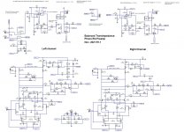
Many thanks for posting the circuit, Bonsai.
In your PCB layout, would you consider adding headers or tap-off points for the output of the MC section only? This would allow a separate flat gain stage to be added which would feed an audio interface for digitising the record. This way one could listen to a record on the RIAA output, while simultaneously archiving the uneq'ed record on a hard drive.
In your PCB layout, would you consider adding headers or tap-off points for the output of the MC section only? This would allow a separate flat gain stage to be added which would feed an audio interface for digitising the record. This way one could listen to a record on the RIAA output, while simultaneously archiving the uneq'ed record on a hard drive.
Last edited:
Yes, I can add those. There'll be a few spins of the board - full RIAA, MC only and Hans suggested a version running off a 5V USB supply - but there will be a noise/OLM penalty because we will have to run the Ic at a lower level.
(BTW there's an error on the circuit - 2 of the opamps have the + and - supply pins swapped)
I restarted a completely new layout yesterday - looking good now.
(BTW there's an error on the circuit - 2 of the opamps have the + and - supply pins swapped)
I restarted a completely new layout yesterday - looking good now.
Don't expect too much of noise differences when going to 5 V USB.
For an 1R Cart difference will be 0.75dB, for 3R 0.57dB, 10R 0.25dB and 30R 0nly 0.04dB.
Hans
For an 1R Cart difference will be 0.75dB, for 3R 0.57dB, 10R 0.25dB and 30R 0nly 0.04dB.
Hans
Brilliant. This one is ticking just about all the boxes.
Yes, I can add those. There'll be a few spins of the board - full RIAA, MC only and Hans suggested a version running off a 5V USB supply - but there will be a noise/OLM penalty because we will have to run the Ic at a lower level.
(BTW there's an error on the circuit - 2 of the opamps have the + and - supply pins swapped)
I restarted a completely new layout yesterday - looking good now.
Don't expect too much of noise differences when going to 5 V USB.
For an 1R Cart difference will be 0.75dB, for 3R 0.57dB, 10R 0.25dB and 30R 0nly 0.04dB.
Hans
Yes, when you quote it in dB it's not too bad! I guess the magic number was to get the RTI spot noise below 300pV/rt Hz.
BTW, are there any preferences for the type of USB connector?
Also, I don't expect the opamp to be happy with just +5V. Will need a neg rail generator.
O.K. that makes it clear why you went to 15mA.
I would advise USB mini B, that's a version that is widely used and doesn't take much space on the PCB.
Regarding the LT6203 that I showed in the circuit diagram, this amp is perfectly happy with just 5 Volt and needs no negative supply.
You can try, because I also gave the .asc file.
I'm using these op-amps in my USB supplied Head Amp, much to my satisfaction.
Hans
O.K. that makes it clear why you went to 15mA.
I would advise USB mini B, that's a version that is widely used and doesn't take much space on the PCB.
Regarding the LT6203 that I showed in the circuit diagram, this amp is perfectly happy with just 5 Volt and needs no negative supply.
You can try, because I also gave the .asc file.
I'm using these op-amps in my USB supplied Head Amp, much to my satisfaction.
Hans
OK - I'll take a look. What's the noise floor on your USB powered H/Amp? - I am assuming this is similar to mediatechnology's design?
Here is a linkHans, can you post a link to your MC stage? Just curious.
Designing a universal diff-in/diff-out Head Amp
Hans
OK - I'll take a look. What's the noise floor on your USB powered H/Amp? - I am assuming this is similar to mediatechnology's design?
Noise is 310pV/rtHz.
Hans
Thanks Hans.
Just wondering if anyone has measured a batch of ZTX 851/951s. If so, how much spread in hfe and VBE did you find?
If you Google it, some people have measured the noise on the internet - that’s how the rbb’ was confirmed ( loys of people suspected it was very low’. See also AoE.
Mediatechnology who posts on here measured a bunch for hFE and was able to match quite easily to within tight limits for hFE and Vbe (see the MP’s thread). I guess you would need to buy quite a few for that though.
Mediatechnology who posts on here measured a bunch for hFE and was able to match quite easily to within tight limits for hFE and Vbe (see the MP’s thread). I guess you would need to buy quite a few for that though.
I measured 20 ZTX851 and 20 ZTX951’s in circuit for their noise.
They where 20/20 all exactly the same, confirming that Rbb is very stable and indeed resp. 1.5R and 1.2R as AoE also measured.
In the TranBal Hfe and Vbe are IMO not very relevant because the servo’s keep both Ic’s, the most important parameter, constant.
Hans
They where 20/20 all exactly the same, confirming that Rbb is very stable and indeed resp. 1.5R and 1.2R as AoE also measured.
In the TranBal Hfe and Vbe are IMO not very relevant because the servo’s keep both Ic’s, the most important parameter, constant.
Hans
I use the Zetex devices all the time and plucked a pair (at random) off the piece of anti-stat foam they reside on -- Vbe and hfe were spot on top of each other.
Yes, the TranBal won’t need matching. I never matched on the X-Altra either and got superb noise and distortion figures - I servo’d out the input offset only. On the builds I did the IC in each half was with a few % (measured across the collector load resistors).
- Home
- Source & Line
- Analogue Source
- Low noise Balanced MC Pre