When you cite me that’s fine, but don’t put words in my mouth that I never said.With the input shorted, I get a reading of -118 dBV at 1 kHz on the QA 401. I make the total system gain 6596.
That gives me an RTI noise of c. 190 pV/rt Hz - nothing like 1.3 or 1,5 nV/rt Hz which is what you and Syn08 are saying.
Clearly we have not reached anywhere near consensus and remain in disagreement.
(You keep bringing up the gain structure - park this to one side until we can get agreement on the noise. The competed preamp takes in MM and MC so the MC part was configured to give c. 5mV out nominally.)
With a shorted input I gave you in #416 figure of 370pV/rtHz@1Khz using your own spice model fully conforming with your measured -118dBV.
So when you don’t even trust your own figures, I wish you like Syn08 did, a sucesfull sales with your Tranbal.
Hans
How can the equivalent input referred noise go from your figure (370pV/rt Hz to 5 or 6 times that after accounting for Rcart noise? Changing the gain does not change the fundamental amplifier RTI noise.
Let’s agree to disagree on this until there is s better understanding of the IPS noise treatment. Until then, l will continue to refine the design. No point in making enemies of each other on this.
😊
Let’s agree to disagree on this until there is s better understanding of the IPS noise treatment. Until then, l will continue to refine the design. No point in making enemies of each other on this.
😊
I’ll try to explain that noise thing when I’m back at home.How can the equivalent input referred noise go from your figure (370pV/rt Hz to 5 or 6 times that after accounting for Rcart noise? Changing the gain does not change the fundamental amplifier RTI noise.
Let’s agree to disagree on this until there is s better understanding of the IPS noise treatment. Until then, l will continue to refine the design. No point in making enemies of each other on this.
😊
And yes I agree, I didn’t spent so much time with the intention to make enemies.
Hans
I've lifted the 220 Ohm resistor that was across the collector loads and the noise sim and readings are all from ~300pV to 790pV RTI whole chain sim 0.1 to 22.1 Ohms. So I agree with you the gain structure is not good, but after fixing this, the performance to my mind very good now.
The CMRR also working well - I can trim 50 Hz CM induced voltage to below the noise floor using the QA401.
I will put some results up shortly.
The CMRR also working well - I can trim 50 Hz CM induced voltage to below the noise floor using the QA401.
I will put some results up shortly.
1) Your diff amp is essence nothing but an inverting amp with an input resistor Ri and a feedback resistor Rfb.I've lifted the 220 Ohm resistor that was across the collector loads and the noise sim and readings are all from ~300pV to 790pV RTI whole chain sim 0.1 to 22.1 Ohms. So I agree with you the gain structure is not good, but after fixing this, the performance to my mind very good now.
The CMRR also working well - I can trim 50 Hz CM induced voltage to below the noise floor using the QA401.
I will put some results up shortly.
You normally don't translate the input voltage Vin into a current with Vin/Ri = In and as a next step calculate the output voltage with Vout =Iin*Rfb,
because simple math shows that Gain = Vout/Vin = (Iin*Rfb)/( In*Rin) = is Rfb/Rin. So forget this step in between converting into a current and back to voltage.
So Gain is Rfb/Ri, where in your case Rfb (2*300//220) and Ri is (Rcart+2*1/Gm).
Noise for an inverting amp is composed by the noise of the active part En1 and the noise and En2 produced by Rfb//Ri.
Noise at the output Enout will be sqrt(En1^2+En2^2)*(1+Rfb/Ri) and noise RTI will be Enout/(Rfb/Ri).
As you see, Ri is part of the noise budget and influences Gain and total noise, but when taking Rcart out of the RTI noise, the basic intrinsic noise will remain practically the same depending on gain because of the two terms (1+Rfb/R1)/(Rfb/Ri), so the higher the gain the less effect Ri has on intrinsic noise calculation.
So far a bit of a simplified theoretical background where I did not include the 2*100R emitter resistors and the open loop gain of the active element determined in your case by Ro.
2) Now making the next step having three stages similar to your design.
Suppose we have an overall gain of 100, and the three stages have an EIN of resp 0.3nV/rtHz, 5nV/rtHz and 10nV/rtHz.
a) three stages have resp a gain of 70, 1,4 and 1 thus in total 100.
The first stagers produces 70*0.3=21nV/rtHz. This added to the second stage of 5nV/rthz gives sqrt(21^2+5^2) =21.6nV/rtHz.
This 21.6nV/rtrHz multiplied by the gain of 1.4 gives 30.2nV/rtHz.
The last stage adds its 10nV/rtHz to this, giving sqrt(30.2^2+10^2) = 31.8 nV/rtHz, Gain is 1 so this is the noise appearing at the output.
Since overall Gain was 100, noise RTI seems to be 31.8/100 = 318pV/rtHz, only 0.5dB more as the original input stage had.
b) three stages have a gain of resp 10, 2 and 5 also 100 in total.
The first stagers produces 10*0.3=3nV/rtHz. This added to the second stage of 5nV/rthz gives sqrt(3^2+5^2) =5.8nV/rtHz.
This 5.8nV/rtrHz multiplied by its gain of 2 gives 11.6nV/rtHz.
The last stage adds its 10nV/rtHz to this, giving sqrt(11.6^2+10^2) = 15.3 nV/rtHz, Gain is 5 so at the output appears 5*15.3 = 76.5nV/rtHz.
Since overall Gain was 100, noise RTI seems to be 76.5/100 = 765pV/rtHz.
Now the noise is 20*log(765/318) = 7.6dB more as in example a) although we used gain stages with the same EIN. This shows that you can't say my Amp has a noise RTI of 300pV/rtHz, no it has changed into 765pV/rtHz.
So lesson learned with low noise input stages is:
Let the first stage amplify as much as possible, preventing the following stages to ruin the noise of the input stage.
Hans
Last edited:
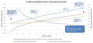
Attached are the latest set of whole signal chain measurements on the TranBal. The 220 Ohm resistor across the 300 Ohm collector load resistors has been removed, raising the TIS front end gain from 6 to 22 with a 22 Ohm source resistor.
Previously, the noise of just the TIS stage only was sim'd at 295 pV.
The sim results below for the whole signal chain now show the 0.1Ohm Rcart RTI noise at 300pV/rt Hz - so just 5 pV more than the TIS stage noise on its own mentioned above. The noise measured on the QA401 shows 455pV - so a difference between sim and measurement of c. 155pV
For the 22.1 Ohm Rcart, the sim noise of the amplifier only is 510pV/rt Hz. The measured noise for the whole signal chain was -120dBV and the total gain 1550 so the RTI measured noise is 645pV.
Given the uncertainties of the system gain at high levels and the actual input resistance with the inputs shorted, it is not easy to get much more accurate results IMV for example a 100 milliOhm higher source resistance at the front end of the amp will make a significant change in the total system gain with a nominal 0.1 Ohm source input resistance. The QA401 readings are not better than to within +-1 dB at -120 dBV.
As already discussed earlier in the thread, there are probably other secondary noise sources (cap leakage etc), but for a fully balanced input stage, the measured noise performance is very good for a 1st cut design like this.
Attachments
Well, just follow the math as given in my posting.Hans, separate question. If I have two cartridges that give 200uV out, but one has an internal resistance of 3 Ohms and the other 5 Ohms, how do we treat this in a TIS stage?
For a voltage input amplifier, the gain will simply be Vout/Vin.
Gain is Rfb/Ri with RfB 2*300//220 = 161R and Ri is Rcart+2*1.Gm, resp 3+3.2 = 6.2 and 5+3.2 = 8.2 giving a gain of resp 161/6.2 = 26.0 and 161/8.2 = 19.6
Hans
Andrew,Attached are the latest set of whole signal chain measurements on the TranBal. The 220 Ohm resistor across the 300 Ohm collector load resistors has been removed, raising the TIS front end gain from 6 to 22 with a 22 Ohm source resistor.
Previously, the noise of just the TIS stage only was sim'd at 295 pV.
The sim results below for the whole signal chain now show the 0.1Ohm Rcart RTI noise at 300pV/rt Hz - so just 5 pV more than the TIS stage noise on its own mentioned above. The noise measured on the QA401 shows 455pV - so a difference between sim and measurement of c. 155pV
For the 22.1 Ohm Rcart, the sim noise of the amplifier only is 510pV/rt Hz. The measured noise for the whole signal chain was -120dBV and the total gain 1550 so the RTI measured noise is 645pV.
Given the uncertainties of the system gain at high levels and the actual input resistance with the inputs shorted, it is not easy to get much more accurate results IMV for example a 100 milliOhm higher source resistance at the front end of the amp will make a significant change in the total system gain with a nominal 0.1 Ohm source input resistance. The QA401 readings are not better than to within +-1 dB at -120 dBV.
As already discussed earlier in the thread, there are probably other secondary noise sources (cap leakage etc), but for a fully balanced input stage, the measured noise performance is very good for a 1st cut design like this.
I have a problem to understand what you say.
The sim results below for the whole signal chain now show the 0.1Ohm Rcart RTI noise at 300pV/rt Hz - so just 5 pV more than the TIS stage noise on its own mentioned above. The noise measured on the QA401 shows 455pV - so a difference between sim and measurement of c. 155pV.
I agree this time with the simmed 300pV/rtHz RTI result, but how does the QA401 come to 455pV/rtHz ?
Did you instruct the QA401 to divide its result by 12000? (=174*2*34.5)
The simmed 300pV/rtHz times 12000 is 3.6uV/rtHz. at the output wher the QA401 is measuring.
When the QA401 is seeing this as (12000*455pV/rtHz =) 5.46 uV/rtHz it would mean that its own noise is sqrt(5.46^2-3.6^2) = 4.1uV/rtHz, true ?
If so, your previous measurement of -118dBV@1Khz with the 220R on the collectors still there and 0.1R at the input is also way off.
So please show what noise your QA401 shows with its input shorted, until then all measured figures can be forgotten.
Hans
The QA401 with the inputs shorted is 154 dBV spot noise at 1kHz.
The sim gain was checked by injecting a 50uV 1kHz signal at the input and monitoring the output of the complete amp for Rcart = 0.1Ohm and then Rcart = 22.1 Ohm.
The QA 401 results are taken by reading the spot noise at 1kHz in dBV and converting this to an input voltage and dividing then by the sim gains. I cannot directly inject a useful signal from the QA401 for very low input signals because there is a series resistor on the generator output. As you can imagine, there is quite some margin for error but I don't have any other way to do it at this point.
Last edited:
You tell what you do, but only partly the what outcome is, making it very hard to react properly.The QA401 with the inputs shorted is 154 dBV spot noise at 1kHz.
The sim gain was checked by injecting a 50uV 1kHz signal at the input and monitoring the output of the complete amp for Rcart = 0.1Ohm and then Rcart = 22.1 Ohm.
The QA 401 results are taken by reading the spot noise at 1kHz in dBV and converting this to an input voltage and dividing then by the sim gains. I cannot directly inject a useful signal from the QA401 for very low input signals because there is a series resistor on the generator output. As you can imagine, there is quite some margin for error but I don't have any other way to do it at this point.
1) I sim a gain of resp 11,995 for 0.1R and 1,585 for 22.1, do you agree ?
2) Why do you need the gain for a noise sim, because as you well know, you can see both onoise and inoise with LTSpice.
All you have to do is to compare the output noise of the sim with the measured noise of the QA401 at the output.
When they correspond, you know from the sim what the inoise is.
3) It seems that your QA401 is capable if measuring the output noise without corrupting it with its own noise.
So again my question, are you sure the QA401 is displaying spectra with a filter bin width of 1Hz.
4) can you send me your .asc file that produces 3.3uV/rthz at the output or 300pV/rtHz RTI.
Don't say that I already have it, that's not good enough.
5) please send me a picture of your QA401 measurement that shows the 455pV/rtHz that you mentioned and tell what gain setting you entered into the QA401.
Could you please answer all 5 questions ?
Hans
1. I sim a different gain for Rcart = 0.1 Ohms of 9800. Same gain at 22.1 Ohms
2. I only sim the gain so I can check the QA401 noise RTI.
3. The QA401 has a selectable rt/Hz feature that normalizes the reading to 1 Hz bandwidth
4. I will send the .ASC file tomorrow
5. The QA 401 does not have a gain setting. It has an attenuator 20 dB or 6 dB. The QA401 display is automatically corrected for the attenuator gain in the software. The pV measurement figures I put on the graph are the QA401 readings divided by the sim’d gain.
Here is the sim I am using to get the above noise figures.
I will email Matt at QuantAssylum later today to discuss the results vs sim - he may have some additional insights on the QA401 side that could explain the difference between sim and measured result (I get 3 dB difference at 0.1 Rcart and about 2.2 dB at Rcart = 22.1 Ohms between sim and measurement)
I will email Matt at QuantAssylum later today to discuss the results vs sim - he may have some additional insights on the QA401 side that could explain the difference between sim and measured result (I get 3 dB difference at 0.1 Rcart and about 2.2 dB at Rcart = 22.1 Ohms between sim and measurement)
Attachments
Your collector current is still wrong with 2.1Volt, this should be 2.5Volt to get the ca. 16.5mA Ic that you confirmed earlier !!Here is the sim I am using to get the above noise figures.
I will email Matt at QuantAssylum later today to discuss the results vs sim - he may have some additional insights on the QA401 side that could explain the difference between sim and measured result (I get 3 dB difference at 0.1 Rcart and about 2.2 dB at Rcart = 22.1 Ohms between sim and measurement)
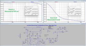
I ran your model unchanged, apart from the 2.5Volt correction, with 0.1R and 22R.
I simmed as well at the diff output and at Vout1
1) 0.1R
This gave 281pVrtHz@1hz RTI from the Diff output and 284pV/rtHz@1Khz as from Vout1, showing that a large gain in the first stage keeps the RTI noise intact,
At the same time Gain diff = 48,9nV/281pV = 174 and gain overall is 3.4u/284p = 11,971 both at 1Khz.
Your QA401 should show 20*log(3.4uV)=-109dBV@1Khz
2) 22R
Here the sim gave 726pV/rtHz RTO from the diff output and 780pV/rtHz from Vout1, an increase in RTI of only 0.6dB, quite good.
Gain diff is 16.8nV/726pV = 23,1 and gain overall is 1.24uV/780pV = 1590 again both at 1Khz.
Your QA401 should show 20*log(1.24uV) = -118dBV.@1Khz.
Taking out the 22R out of the 780pV/rtHz@1Khz RTI as seen from Vout1 gives sqrt(780^2-610^2) = 486pV/rtHz RTI.
Making the same calculation from the diff output gives sqrt(728^2-610^2) = 397pV/.rtHz@1Khz
The difference between the 486pV and 397pV is caused by the relatively low gain of 23.1 of the diff stage, but compared to the 610pV/rtHz from the 22R it is rather harmless.
3) So to conclude, could you tell what readings your QA401 is giving with 0.1R and 22R at 1Khz, and how close this is to -109dBV and -118dBV for rep 0.1R and 22R.
Hans
Attachments
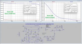
Agree the model emitter current was not correct - 13mA vs 16.5mA target. The preamp has the correct current - I just remeasured voltage across the 100 Ohm emitter resistors at 1.65V = 16.5mA
With the input shorted the reading is -108.5 dB and at 22 Ohms the reading is -117.4 dB. You can say both these readings are +-0.2dB because of the display grass.
Please note, there is a +-1 dB difference in the readings from day to day - I guess this is related to drift or thermal issues since they will have an effect at these very low signal levels.
So there we are, your QA401 readings are ca. 0.5 above the sim.Agree the model emitter current was not correct - 13mA vs 16.5mA target. The preamp has the correct current - I just remeasured voltage across the 100 Ohm emitter resistors at 1.65V = 16.5mA
With the input shorted the reading is -108.5 dB and at 22 Ohms the reading is -117.4 dB. You can say both these readings are +-0.2dB because of the display grass.
Please note, there is a +-1 dB difference in the readings from day to day - I guess this is related to drift or thermal issues since they will have an effect at these very low signal levels.
That’s what corresponds with my sim versus measurement experience.
You now have an LTSpice model that can be used to find the optimal gain settings for the three stages.
Hans
- Home
- Source & Line
- Analogue Source
- Low noise Balanced MC Pre