Very true, that´s why I mentioned that "measuring better as LTSpice predicts" is an utopia.Hans, indeed Spice is excellent for determining the equivalent Johnson noise. It replaces the real part of any reactance with it's equivalent thermal noise source, then does the math. However, there are several noise mechanisms that are by default poorly or not at all included:
- Leakage current noises (such as in electrolytic capacitors)
- Excess noise. Excess noise models in passive components models are not included, while for active components they are crude and anyway expected in the device models.
- Noise corner frequencies, once again expected in the device models, which rarely include them.
- Large signal noise injection mechanisms are not included, all noise models are considered linear, and linear analysis is used to determine the noise budget.
You will always measure a somewhat higher level because of all the reasons you gave.
And as we experienced with the Polymer caps, it can also make you aware of unacceptable excessive noise.
Hans
Andrew, when simulating up to behind the SE converter using a 22R Cart, I already get a spot noise of 18.2nV/rtHz@1Khz.Are we all in agreement that with a 22 Ohm resistor across the TranBal inputs, the QA401 spot noise reading of -121 to -122 dBV is reality and the QA401 is not giving a bad answer?
Can we agree that with this info and the exact gains per stage, we can calculate accurately the total RTI noise (amp plus 22 Ohm resistor)?
Can we agree if we subtract the noise current of the 22 Ohm RMS style we get the total amp only input referred current noise and from this can state a notional noise voltage (yes, I am choosing my words carefully to avoid confusion)?
Finally, if that total noise after subtraction is then at or very close to the sim’d value of 292pV with the sim’d inputs shorted, it confirms the noise performance of the amplifier?
Optimising the signal chain gains for lower noise is a separate subject. We should not even attempt that without establishing the veracity of the measurement methodology.
Given that modelling a system and then measuring the resultant performance of a practical case is de riguer in many areas of science and engineering (aerospace, biology, electronics are a few examples), I fail to see what the fuss is about on my methodology. I’ve done exactly what is considered normal practice.
Rather than hurl insults or claim the TranBal does not meet spec, perhaps someone would calculate the noise on the input of the TIS given the model output of 11.5 nV. I have shown my calculations and reasoning - repeated 2 or 3 times above. Explain why it is wrong. I’ve made it clear why Syn08’s treatment is incorrect.
I really don’t want poison this thread with anymore bs. If we cannot have gentlemanly discussion, please leave the thread.
Multiply this with 34 and you have 619nV/rtHz or -124.2 dBV, but .... only when your filter bin width is corrected to 1Hz.
So if you did correct for a 1Hz bin, you seem to have lost some additional 2 to 3 dB in the Riaa amp.
Taking your best -122dBV or 794nV/rtHz /34/2/6.27 = 1.86nV/rtHz@1Khz RTI.
Neglecting the effect of the 100R emitter resistors, when taking out the noise from the 22R, this becomes sqrt(1,86^2-0.61^2) = 1.76nV/rtHz
This a way from the 292pV/rtHz that you mention, so how did you get this figure ?
Hans
Taking your best -122dBV or 794nV/rtHz /34/2/6.27 = 1.86nV/rtHz@1Khz RTI.
Neglecting the effect of the 100R emitter resistors, when taking out the noise from the 22R, this becomes sqrt(1,86^2-0.61^2) = 1.76nV/rtHz
This a way from the 292pV/rtHz that you mention, so how did you get this figure ?
About what I got with pen and pencil, so either the input stage is noisy as hell (servo noise injection? electrolytic leakage?), or the output noise measurements are flat wrong, or the signal chain gains are wrong. BTW, Are you sure the op amps models have noise simulation included?
But I am sure you are confusing voltage noise and current noise too, admit it.
I ticked the rt Hz box on the QA401 so the spot noise is for a 1 Hz BW. My reading is 871 nV/rt HzHans
You are dividing the output of the TIS by 6. If I take any TIS generating a voltage across a load resistor, how can you just divide that by a voltage gain to find the input voltage. you cant. you have to calculate the input current and multiply that by the source resistor on the input to derive the driving voltage. So I divide my TIS output voltage by the load resistor to determine the current. This is the total noise current from which I subtrace the 22 Ohm noise current and I am left with 83pA/rt Hz. I multiply this by the input resistance and get 292 pV equivalent input noise. In reality, better specified as 83pA/rt Hz
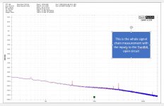
Here is the whole signal chain noise analysis. I got 340pV/rt Hz with 0.1 Ohm input resistance - call me a liar for 48 pV/rt Hz 😀
Results: Sim 343pV/rt Hz with 0.1Ohm input resistor. With 22 Ohm resistor 1.35 nV/rt Hz
Front end TIS plus bal > unbal only is 295 pV/rt Hz - to the additional 48 pV/rt Hz is coming from the RIAA amp
You can play with the file here:-
Results: Sim 343pV/rt Hz with 0.1Ohm input resistor. With 22 Ohm resistor 1.35 nV/rt Hz
Front end TIS plus bal > unbal only is 295 pV/rt Hz - to the additional 48 pV/rt Hz is coming from the RIAA amp
You can play with the file here:-
Attachments
In my model the first op amp is noiseless, because all noise is projected in the surrounding resistors, and the second op amp for Diff to Se conversion is spot on with the two parameters visible in the model, with En=6,36nV/rtHz and Enk=400Hz, plus the two 400R resistors.About what I got with pen and pencil, so either the input stage is noisy as hell (servo noise injection? electrolytic leakage?), or the output noise measurements are flat wrong, or the signal chain gains are wrong. BTW, Are you sure the op amps models have noise simulation included?
But I am sure you are confusing voltage noise and current noise too, admit it.
The reason for the high noise is because the Diff to Se converter is adding 6dB to the diff amp's noise and the Riaa amp another 2dB.
The noise RTI of the diff amp alone with 22R is 758nV/rtHz.
Multiply this resp with 6.27*2*34 and you have 323nV/rtHz when Diff to Se and Riaa would have been noiseless.
However the Diff to Se adds 6 dB and the Riaa another 2dB.
This additional 8dB changes the 323nV/rtHz to 811nV/rtHz or -121.8dBV, that's it, so no servo noise injection or leaking caps, just straightforward.
Hans
With all respect, you are comparing apples to pears and btw nobody is calling you whatever sort of species.Here is the whole signal chain noise analysis. I got 340pV/rt Hz with 0.1 Ohm input resistance - call me a liar for 48 pV/rt Hz 😀
Results: Sim 343pV/rt Hz with 0.1Ohm input resistor. With 22 Ohm resistor 1.35 nV/rt Hz
Front end TIS plus bal > unbal only is 295 pV/rt Hz - to the additional 48 pV/rt Hz is coming from the RIAA amp
You can play with the file here:-
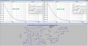
With a 0.1R cart the gain of the diff amp increases considerably from 6.27 to 48.7 making the noise contribution of Diff to Se and Riaa stages a whole lot less.
After the Diff to Se, I sim 31.6nV/rtHz with a 0,1R Cart.
Divide this by 2*48.7 and you have 323pV/rtHz (not your 343pV/rtHz) and with the Diff alone I sim 282pV/rtHz RTI.
So in this case the diff to Se is only adding 323/282 = 1.18dB additional noise instead of the 6dB when using a 22R Cart.
Hans
Sorry, but this is incorrect.I ticked the rt Hz box on the QA401 so the spot noise is for a 1 Hz BW. My reading is 871 nV/rt Hz
You are dividing the output of the TIS by 6. If I take any TIS generating a voltage across a load resistor, how can you just divide that by a voltage gain to find the input voltage. you cant. you have to calculate the input current and multiply that by the source resistor on the input to derive the driving voltage. So I divide my TIS output voltage by the load resistor to determine the current. This is the total noise current from which I subtrace the 22 Ohm noise current and I am left with 83pA/rt Hz. I multiply this by the input resistance and get 292 pV equivalent input noise. In reality, better specified as 83pA/rt Hz
Hans
What is incorrect?
We are to within a few tens of pV at 343 pV or 1 dB and this matches up pretty closely to the QA401 reading of c. -122 dBV - especially given the uncertainty of the reading due to the display grass.
There may be some cleaning up of the calculations to take into account the resistor noise sources around the front end other than just the 22 Ohm but that’s it.
Last edited:
With all respect, you are comparing apples to pears and btw nobody is calling you whatever sort of species.
With a 0.1R cart the gain of the diff amp increases considerably from 6.27 to 48.7 making the noise contribution of Diff to Se and Riaa stages a whole lot less.
After the Diff to Se, I sim 31.6nV/rtHz with a 0,1R Cart.
Divide this by 2*48.7 and you have 323pV/rtHz (not your 343pV/rtHz) and with the Diff alone I sim 282pV/rtHz RTI.
So in this case the diff to Se is only adding 323/282 = 1.18dB additional noise instead of the 6dB when using a 22R Cart.
Hans
Andrew,
Saying that what you do is incorrect is one thing, but I had to figure out the best way to explain why.
So here is my complete answer now by using your (complex) voltage to current and vice versa again to voltage calculation.
Look at the attached image.
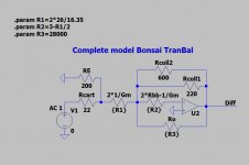
When dividing the measured output voltage of 871 nV/rtHz by 2*34 gives 12.8nV/rtHz at the output of the Diff stage.
To convert this into a current, divide this by 600//220=161R giving you 79.5pA/rtHz.
Multiply the 79.5pA/rtHz with (22R//200R + 2*1/Gm) = 23R giving you 1.83nVrtHz.
Be aware that part of this noise is also produced produced by 2*Rbb-1/Gm, being outside the current loop, but this part would add little to this calculation so I will leave it here.
Subtract from this 1.83nV/rtHz the noise produced by the 22R//200R and you get sqrt(1.83^2-0.58^2) = 1.73nV/rtHz.
Compare this to my to my posting #202 where, by using a gain of 6.27, I came to 1.76nN/rtHz.
Hans
Saying that what you do is incorrect is one thing, but I had to figure out the best way to explain why.
So here is my complete answer now by using your (complex) voltage to current and vice versa again to voltage calculation.
Look at the attached image.
When dividing the measured output voltage of 871 nV/rtHz by 2*34 gives 12.8nV/rtHz at the output of the Diff stage.
To convert this into a current, divide this by 600//220=161R giving you 79.5pA/rtHz.
Multiply the 79.5pA/rtHz with (22R//200R + 2*1/Gm) = 23R giving you 1.83nVrtHz.
Be aware that part of this noise is also produced produced by 2*Rbb-1/Gm, being outside the current loop, but this part would add little to this calculation so I will leave it here.
Subtract from this 1.83nV/rtHz the noise produced by the 22R//200R and you get sqrt(1.83^2-0.58^2) = 1.73nV/rtHz.
Compare this to my to my posting #202 where, by using a gain of 6.27, I came to 1.76nN/rtHz.
Hans
Attachments
But we are about the amp only noise. You say it’s 1.73nV and the sim gives a totally different result ie 343pV. How do you explain that?Andrew,
Saying that what you do is incorrect is one thing, but I had to figure out the best way to explain why.
So here is my complete answer now by using your (complex) voltage to current and vice versa again to voltage calculation.
Look at the attached image.
When dividing the measured output voltage of 871 nV/rtHz by 2*34 gives 12.8nV/rtHz at the output of the Diff stage.
To convert this into a current, divide this by 600//220=161R giving you 79.5pA/rtHz.
Multiply the 79.5pA/rtHz with (22R//200R + 2*1/Gm) = 23R giving you 1.83nVrtHz.
Be aware that part of this noise is also produced produced by 2*Rbb-1/Gm, being outside the current loop, but this part would add little to this calculation so I will leave it here.
Subtract from this 1.83nV/rtHz the noise produced by the 22R//200R and you get sqrt(1.83^2-0.58^2) = 1.73nV/rtHz.
Compare this to my to my posting #202 where, by using a gain of 6.27, I came to 1.76nN/rtHz.
Hans
Ok my sim doesn’t, so please make your sim available with the 22R and I’ll respond to it.But we are about the amp only noise. You say it’s 1.73nV and the sim gives a totally different result ie 343pV. How do you explain that?
Hans
I posted my sim .ASC file up earlier - you can change the input R and run it at 0.1 or 22 Ohm.Ok my sim doesn’t, so please make your sim available with the 22R and I’ll respond to it.
Hans
At 0.1 Input R the RTI noise is 343 pV/rt Hz
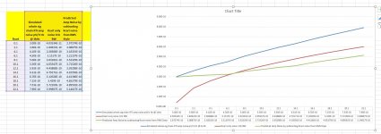
I used the sim file I posted earlier and stepped Rcart from 0.1 to 22 Ohm in 2 Ohm increments then put this into a spread sheet attached below.
This does show an increase in RTI noise, but not at the levels you get by simply dividing the noise at the TIS by 6 - its more in line with my approach.
However, my preferred way forward is to to try to understand why this discrepancy exists - its c. 2:1 (I'm seeing half the noise you are predicting).
Later tonight I will disconnect the servo and short the inputs and do a reading and then also do one with the input open circuit so the input stage noise contribution is rb' plus the 4 resistors around the front end - 2 x 100 and 2 x 300).
Attachments
Sorry Andrew,I posted my sim .ASC file up earlier - you can change the input R and run it at 0.1 or 22 Ohm.
At 0.1 Input R the RTI noise is 343 pV/rt Hz
I'm more than willing to give the feedback you are asking for, but please stick to the things you have written.
You mentioned to have measured 871nV/rtHz@1Khz with 22R and when taking out the 22R you ended up with 292pV/rtHz, true?
The Circuit diagram you showed had the OPA1654 for the Diff to Se converter and you confirmed an IC of ca. 16.5mA true ?
But in the .ASC file you made available, IC is 12.9mA and the Diff to SE converter has the LT1792, having roughly the same noise, but a knee point at 30Hz instead of 400Hz that the OP1654 has, how unthoughtful !
Using your incorrect model with 22R, I get 555nV/rtHz@1Khz, incomparable with your measured 871nV/rtHz@1Khz.
However when running your .asc model, with the correct collector current, the OPA1654 op-amps and aiming for 850nV/rtHz@1Khz at the output, just a bit lower as what you measured to compensate for the fact that measurement is always a few percent higher, I get 1.97nV/rtHz@1Khz RTI.
Subtract the 22R from this budget and you get sqrt(1.97^2-0.61^2) = 1.87nV/rtHz@1Khz at the input.
Simply a bad figure, above a simple AD797 and not at all coming in the direction of the 292pV/rtHz@1Khz that you mentioned initially, caused by a bad balance of gain between the three stages.
Now when following the sudden switch that you made, referring to a 0.1R Cart resistor, the adjusted model shows a simmed noise RTI of 370pV/rtHz@1Khz.
This 370pV/rtHz is quite a bit lower as the 1.87nV/rtHz with 22R, both at 1Khz, just because gain of the diff stage went from 6 to 48, making the noise contribution of the following two stages a lot lesser.
But in the end, this 370pV/rtHz is still a long way from the 282pV/rtHz that the diff amp alone achieves with 0.1R.
So, how can you refer to results that are way off reality, I'm disappointed.
Hans
Attachments
I shorted the TranBal inputs and then checked that the emitter currents remained the same - they are ok and the currents in each half are tightly balanced - one channel is 16.5mA and the other 17.2mA. Attached below is the QA401 measurement of this test.
I disagree that we have huge discrepancieiven the issues I already made clear with measuring the noise. We can fiddle around with opamps etc, but in the end of the day, what is the native noise of the circuit with 0 input resistance? I remember on the MC Headamp thread, people asked me (incl. Syn08) why I didn't sim with 0 Ohms for Rcart instead of the 5 and 10 ohm I used.
Of course the gain will change with Rcart - but like I have explained, IMV the correct RTI noise is arrived at by considering the noise current - the TIS does not respond correctly to injecting a voltage into it. The pV/rt Hz figures quoted are effectively equivalent thermal noise - its noise current that has to be considered (here I mean not the current noise as spec'd for example by In in an opamp data sheet but just the source resistance thermal noise voltage divided by the resistance)
As for the .ASC file I put up, please feel free to change opamps etc. - you used idealized opamps that as far as I can tell did not model opamp noise - that's why I used LT1792 with c. 3.5 nV/rt Hz. The AD797 is spec'd at 0.9nV/rt Hz. How do you make a fully diff input with 1 device and keep 0.9nV/rt Hz? So, sorry , I do not agree that it is little better than an AD797.
Hans, we are looking at 1kHz spot noise - please, the 1/f noise is a side issue. We only need to worry about that when we look at integrated noise.Sorry Andrew,
I'm more than willing to give the feedback you are asking for, but please stick to the things you have written.
You mentioned to have measured 871nV/rtHz@1Khz with 22R and when taking out the 22R you ended up with 292pV/rtHz, true?
The Circuit diagram you showed had the OPA1654 for the Diff to Se converter and you confirmed an IC of ca. 16.5mA true ?
But in the .ASC file you made available, IC is 12.9mA and the Diff to SE converter has the LT1792, having roughly the same noise, but a knee point at 30Hz instead of 400Hz that the OP1654 has, how unthoughtful !
Using your incorrect model with 22R, I get 555nV/rtHz@1Khz, incomparable with your measured 871nV/rtHz@1Khz.
However when running your .asc model, with the correct collector current, the OPA1654 op-amps and aiming for 850nV/rtHz@1Khz at the output, just a bit lower as what you measured to compensate for the fact that measurement is always a few percent higher, I get 1.97nV/rtHz@1Khz RTI.
Subtract the 22R from this budget and you get sqrt(1.97^2-0.61^2) = 1.87nV/rtHz@1Khz at the input.
Simply a bad figure, above a simple AD797 and not at all coming in the direction of the 292pV/rtHz@1Khz that you mentioned initially, caused by a bad balance of gain between the three stages.
Now when following the sudden switch that you made, referring to a 0.1R Cart resistor, the adjusted model shows a simmed noise RTI of 370pV/rtHz@1Khz.
This 370pV/rtHz is quite a bit lower as the 1.87nV/rtHz with 22R, both at 1Khz, just because gain of the diff stage went from 6 to 48, making the noise contribution of the following two stages a lot lesser.
But in the end, this 370pV/rtHz is still a long way from the 282pV/rtHz that the diff amp alone achieves with 0.1R.
So, how can you refer to results that are way off reality, I'm disappointed.
Hans
I disagree that we have huge discrepancieiven the issues I already made clear with measuring the noise. We can fiddle around with opamps etc, but in the end of the day, what is the native noise of the circuit with 0 input resistance? I remember on the MC Headamp thread, people asked me (incl. Syn08) why I didn't sim with 0 Ohms for Rcart instead of the 5 and 10 ohm I used.
Of course the gain will change with Rcart - but like I have explained, IMV the correct RTI noise is arrived at by considering the noise current - the TIS does not respond correctly to injecting a voltage into it. The pV/rt Hz figures quoted are effectively equivalent thermal noise - its noise current that has to be considered (here I mean not the current noise as spec'd for example by In in an opamp data sheet but just the source resistance thermal noise voltage divided by the resistance)
As for the .ASC file I put up, please feel free to change opamps etc. - you used idealized opamps that as far as I can tell did not model opamp noise - that's why I used LT1792 with c. 3.5 nV/rt Hz. The AD797 is spec'd at 0.9nV/rt Hz. How do you make a fully diff input with 1 device and keep 0.9nV/rt Hz? So, sorry , I do not agree that it is little better than an AD797.
Attachments
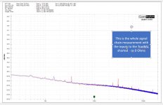
This is my last attempt to show the inconstancies in your information. Here is what you said in #399I shorted the TranBal inputs and then checked that the emitter currents remained the same - they are ok and the currents in each half are tightly balanced - one channel is 16.5mA and the other 17.2mA. Attached below is the QA401 measurement of this test.
Hans, we are looking at 1kHz spot noise - please, the 1/f noise is a side issue. We only need to worry about that when we look at integrated noise.
I disagree that we have huge discrepancieiven the issues I already made clear with measuring the noise. We can fiddle around with opamps etc, but in the end of the day, what is the native noise of the circuit with 0 input resistance? I remember on the MC Headamp thread, people asked me (incl. Syn08) why I didn't sim with 0 Ohms for Rcart instead of the 5 and 10 ohm I used.
Of course the gain will change with Rcart - but like I have explained, IMV the correct RTI noise is arrived at by considering the noise current - the TIS does not respond correctly to injecting a voltage into it. The pV/rt Hz figures quoted are effectively equivalent thermal noise - its noise current that has to be considered (here I mean not the current noise as spec'd for example by In in an opamp data sheet but just the source resistance thermal noise voltage divided by the resistance)
As for the .ASC file I put up, please feel free to change opamps etc. - you used idealized opamps that as far as I can tell did not model opamp noise - that's why I used LT1792 with c. 3.5 nV/rt Hz. The AD797 is spec'd at 0.9nV/rt Hz. How do you make a fully diff input with 1 device and keep 0.9nV/rt Hz? So, sorry , I do not agree that it is little better than an AD797.
Are we all in agreement that with a 22 Ohm resistor across the TranBal inputs, the QA401 spot noise reading of -121 to -122 dBV is reality and the QA401 is not giving a bad answer?
Can we agree that with this info and the exact gains per stage, we can calculate accurately the total RTI noise (amp plus 22 Ohm resistor)?
Can we agree if we subtract the noise current of the 22 Ohm RMS style we get the total amp only input referred current noise and from this can state a notional noise voltage (yes, I am choosing my words carefully to avoid confusion)?
Finally, if that total noise after subtraction is then at or very close to the sim’d value of 292pV with the sim’d inputs shorted, it confirms the noise performance of the amplifier?
The above is what you repeated several times in #374,#376, #389 and above in #399.
With 22R you got 871nV/rtHz@1Khz or -121.2dBV, which working back gave you 292pV/rtHz at the input when taking 22R out of the equation.
In the above simulation in #416 I have shown that this 871nv/rtHz results in 1.87nV/rtHz@1Khz without the 22R, 6 times larger as your 292pV, which led me to the remark that this can be improved by an AD797. But this remark was for 22R, where the balance in gain from your gain stages is far from optimal.
Look in Linear Audio Vol12 and you will find a AD797 based diff MC amp with a noise RTI of 1.5nV/rtHz@1Khz.
Now you are showing a recording that is at ca. -118dBV@1Khz or 1.26uV@1Khz with Rcart is zero.
Look again at my sim in #416 and you will see that my simmed projection is spot on with 1.22uV/rtHz@1Khz, which gave an RTI result of 370pV/rtHz@1KHz.
Contrary to what you thought, I used exactly modelled op-amps, with the essential parameters visible above them.
How else could the results have corresponded so well with your measurements ?
What I'm trying to make you aware of is that your diff amp stage has a nice voltage noise figure, but this is completely spoiled by wrong gain settings for the gain stages. You should set a target that whatever the load is up to 50R, that noise RTI will never be greater than ..... after subtracting the Carts noise from the RTI noise and work back from there. And it must be clear that the 1.87pV/rtHz without 22R for a 22R cart is waaaay too large.
The 292pV/rtHz noise performance that you think to have confirmed in your #399 posting is a nonsense figure, that Syn08 also tried you to convince of.
But some little voice in my head tells me that you have a problem to accept this.
Hans
With the input shorted, I get a reading of -118 dBV at 1 kHz on the QA 401. I make the total system gain 6596.
That gives me an RTI noise of c. 190 pV/rt Hz - nothing like 1.3 or 1,5 nV/rt Hz which is what you and Syn08 are saying.
Clearly we have not reached anywhere near consensus and remain in disagreement.
(You keep bringing up the gain structure - park this to one side until we can get agreement on the noise. The competed preamp takes in MM and MC so the MC part was configured to give c. 5mV out nominally.)
- Home
- Source & Line
- Analogue Source
- Low noise Balanced MC Pre