Sorry, it doesn’t add up. If you divide -121.4dB (871nV/rtHz) by 34 (RIAA gain), 2 (bal to SE), and 6 (input stage) you are far away from your simulated 292pV/rtHz RTI.I got a reading of c. -121.4 dBV on the output and my noise calculation supports that. The complete signal chain sim also supports the -121.4 dBV figure. The front end stage (TIS + bal to SE) sim gives 292pV/rt Hz which is what I used to calculate up to the output.
Gerhard Hoffman also reported the same about 2 years ago. One of the IEEE journals has an article on the mechanism, but I don't have access to it.Be very careful with the base decoupling electrolytics. These need to be with extremely low leakage. Otherwise, the leakage will have a noise (like any current) which will get injected straight in the transistors bases, and amplified, screwing the whole noise budget.
AndrewHans, I calculate spot noise at 1 kHz where the gain is flat. This is a good figure of merit and allows instant confirmation of the RTI noise against the sim.
Sorry, I don’t get your point about the bal> SE converter. Here is how I handled it:- Each opamp is 5 nV/rt Hz, RMS summed this is still 5 nV/rt Hz for both opamp. I ignored the thermal noise of the 220 Ohm gain setting resistors.
For the total integrated noise, you can get this from the sim very easily and also just read it off the QA401. To calculate this means splitting up the audio band, calculating noise for each band then RMS summing it because of the RIAA EQ. A job for a spread sheet - the spot noise method is much easier.
A short reaction before going into more depth: the OPA1654 has 4,5 nV/rtHz. Since the two produce uncorrelated noise, their sum is not the 2*5=10nV/rtHz but 6.36nV/rtHz.
When using the last circuit diagram that you gave, there is a volage divider to bias the two ZTX bases composed of 5k6//5K6 plus 1K020 from +10Volt to gnd. giving IC=16.35mA, is this still correct ?
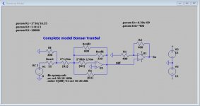
See diagram below that very accurately conforms to your model, in this case for Ic=16.35mA
Measured at the Diff output, noise RTI is 758pV/rtHz@1Khz with a 6.27 gain.
And behind the Diff to Se converter, noise is 1.53nV/rtHz@1Khz, 100% more.
So this combination of gain settings is not very rewarding from a noise point of view.
Much better would have been a bigger gain in the diff stage followed by attenuation instead of gain in the Diff to Se stage.
When replacing the 220R collector resistor by a 702R resistor and giving the Diff to SE converter a gain of 1 instead of 2 to, keeps the overall gain identical but let de noise RTI as measured behind the Se converter drop from 1.53nV/rtHz to 980pV/rtHz !
Hans
Attachments

In your example above you have mixed voltage and current up.Sorry, it doesn’t add up. If you divide -121.4dB (871nV/rtHz) by 34 (RIAA gain), 2 (bal to SE), and 6 (input stage) you are far away from your simulated 292pV/rtHz RTI.
871 nV/34 = 25.5nV
25.6nV/2 = 12.8nV at the output of the TIS
Now divide 12.8nV by 132 to get the input noise current =97pA which is within 10pA of the 87pA figure I calculated.
I have no idea what you are talking about, I thought we are in the voltage gain and voltage RTI noise domain.
Your back tracking calculations from the OP to the input are correct up until the output of the TIS - we are in agreement. But then you take the TIS output voltage and divide by 6 to arrive at an input voltage which is not correct.
I’m saying take the TIS output voltage and divide it by the collector load resistor (132 ohms) and the result gives you the correct answer for the total input noise current to within a small fraction of a dB. Subtract RMS style from that the 22 Ohms noise current and the result is c. 292 pV/rt Hz amplifier only thermal noise.
The 292pV/rt Hz is the equivalent thermal input noise voltage
Last edited:
You are correct about the noise on the bal to SE converter - my oversight.Andrew
A short reaction before going into more depth: the OPA1654 has 4,5 nV/rtHz. Since the two produce uncorrelated noise, their sum is not the 2*5=10nV/rtHz but 6.36nV/rtHz.
When using the last circuit diagram that you gave, there is a volage divider to bias the two ZTX bases composed of 5k6//5K6 plus 1K020 from +10Volt to gnd. giving IC=16.35mA, is this still correct ?
See diagram below that very accurately conforms to your model, in this case for Ic=16.35mA
Measured at the Diff output, noise RTI is 758pV/rtHz@1Khz with a 6.27 gain.
And behind the Diff to Se converter, noise is 1.53nV/rtHz@1Khz, 100% more.
So this combination of gain settings is not very rewarding from a noise point of view.
Much better would have been a bigger gain in the diff stage followed by attenuation instead of gain in the Diff to Se stage.
When replacing the 220R collector resistor by a 702R resistor and giving the Diff to SE converter a gain of 1 instead of 2 to, keeps the overall gain identical but let de noise RTI as measured behind the Se converter drop from 1.53nV/rtHz to 980pV/rtHz !
Hans
There will be opportunities to tweak the signal chain gains to improve the overall noise - something to work on in the next few weeks.
The collector currents I measured were 1.65V across each 100 Ohm emitter resistor- so indeed 16.5 mA per side.
Dividing by 6 renders the noise that includes the 22ohm resistor. You could subtract the resistor noise and any voltage divider effect and get the intrinsic amp RTI voltage noise right away.Your back tracking calculations from the OP to the input are correct up until the output of the TIS - we are in agreement. But then you take the TIS output voltage and divide by 6 to arrive at an input voltage which is not correct.
I’m saying take the TIS output voltage and divide it by the collector load resistor (132 ohms) and the result gives you the correct answer for the total input noise current to within a small fraction of a dB. Subtract RMS style from that the 22 Ohms noise current and the result is c. 292 pV/rt Hz amplifier only thermal noise.
The 292pV/rt Hz is the equivalent thermal input noise voltage
How you get from the input noise current to that 292pV/rtHz voltage noise without going into the circuit details must be your well guarded secret. I’ll stop here, since I identify the known pattern of denying evidence and stubborn refusal to admit logical arguments.
This is just not correct Syn08. My calculation and methodology have been absolutely clear - just go through the posts above and the graphic I posted up showing how I did it. The circuit is published in this thread - quite open and anyone can look at it.
When there is no input voltage on the TIS input and it is shorted together with a 22 Ohm resistor, the only thing flowing is noise current and the input voltage is very low since the TIS input impedance is low - c. 3.5 Ohms x the noise current is what you will see - not c. 2 nV. The spot noise of a 22 Ohm resistor is 604pV/rt Hz
Once again here is the methodology
1. Calculate the total noise current from 22+3.5 Ohms = c. 87pA/rt Hz (27pA is from the 22 Ohm Resistor and 83pA/rt Hz is from the amplifier c.f. 292pV/rt Hz obtained from sim divided by 3.5 Ohms
2. Multiply 87pA by 132 to get the TIS output noise voltage which is 11.5nV
3. Multiply by 2 to get 25 nV
4. Multiply by 34 to get 871 nV = ~-122 dBV spot noise at 1kHz
When you calculated backwards we were in agreement until the TIS output voltage - but then you divided it by 6 and got c. 2nV input noise which is wrong. You are mixing current and voltage up on the TIS input. Don't do that.
This is just not correct Syn08. My calculation and methodology have been absolutely clear - just go through the posts above and the graphic I posted up showing how I did it. The circuit is published in this thread - quite open and anyone can look at it.
When there is no input voltage on the TIS input and it is shorted together with a 22 Ohm resistor, the only thing flowing is noise current and the input voltage is very low since the TIS input impedance is low - c. 3.5 Ohms x the noise current is what you will see - not c. 2 nV. The spot noise of a 22 Ohm resistor is 604pV/rt Hz
Once again here is the methodology
1. Calculate the total noise current from 22+3.5 Ohms = c. 87pA/rt Hz (27pA is from the 22 Ohm Resistor and 83pA/rt Hz is from the amplifier c.f. 292pV/rt Hz obtained from sim divided by 3.5 Ohms
Understood, so you took a RTI voltage noise value from simulation (292pV/rtHz), and used it to calculate the input current noise. Then used the result to calculate the total RTI voltage noise and got (what a surprise!) 292pV/rtHz. You must be joking.
If you really want the RTI voltage noise of the intrinsic amplifier, just measure the ******* thing with the input short (no 22ohm) and be done with it. The input stage gain with input short is Au=-gm*Rl = 0.0165*40*132~87 No need to use any simulation values to adjust the measurement to your expectations. BTW, I am not confusing anything, it's rather your known limited capability to follow a logical argument. My question was simple and you failed to answer repeatedly.
Over and out.
Last edited:
This is just not correct Syn08. My calculation and methodology have been absolutely clear - just go through the posts above and the graphic I posted up showing how I did it. The circuit is published in this thread - quite open and anyone can look at it.
When there is no input voltage on the TIS input and it is shorted together with a 22 Ohm resistor, the only thing flowing is noise current and the input voltage is very low since the TIS input impedance is low - c. 3.5 Ohms x the noise current is what you will see - not c. 2 nV. The spot noise of a 22 Ohm resistor is 604pV/rt Hz
Once again here is the methodology
1. Calculate the total noise current from 22+3.5 Ohms = c. 87pA/rt Hz (27pA is from the 22 Ohm Resistor and 83pA/rt Hz is from the amplifier c.f. 292pV/rt Hz obtained from sim divided by 3.5 Ohms
2. Multiply 87pA by 132 to get the TIS output noise voltage which is 11.5nV
3. Multiply by 2 to get 25 nV
4. Multiply by 34 to get 871 nV = ~-122 dBV spot noise at 1kHz
When you calculated backwards we were in agreement until the TIS output voltage - but then you divided it by 6 and got c. 2nV input noise which is wrong. You are mixing current and voltage up on the TIS input. Don't do that.
I did measure it. And guess what? It matches the sim 100%. So model = theoryUnderstood, so you took a RTI voltage noise value from simulation (292pV/rtHz), and used it to calculate the input current noise. Then used the result to calculate the total RTI voltage noise and got (what a surprise!) 292pV/rtHz. You must be joking.
If you really want the RTI voltage noise of the intrinsic amplifier, just measure the ******* thing with the input short (no 22ohm) and be done with it. The input stage gain with input short is Au=-gm*Rl = 0.0165*40*132~87 No need to use any simulation values to adjust the measurement to your expectations. BTW, I am not confusing anything, it's rather your known limited capability to follow a logical argument. My question was simple and you failed to answer repeatedly.
Over and out.
You’ve mixed voltage and current terms. Just admit it.
Peace
Here are the noise figures with Rcart is 1mR, resulting in 279pV/rtHz RTI as seen from the diff output, even below the 293pVrtHz that you calculated.This is just not correct Syn08. My calculation and methodology have been absolutely clear - just go through the posts above and the graphic I posted up showing how I did it. The circuit is published in this thread - quite open and anyone can look at it.
When there is no input voltage on the TIS input and it is shorted together with a 22 Ohm resistor, the only thing flowing is noise current and the input voltage is very low since the TIS input impedance is low - c. 3.5 Ohms x the noise current is what you will see - not c. 2 nV. The spot noise of a 22 Ohm resistor is 604pV/rt Hz
Once again here is the methodology
1. Calculate the total noise current from 22+3.5 Ohms = c. 87pA/rt Hz (27pA is from the 22 Ohm Resistor and 83pA/rt Hz is from the amplifier c.f. 292pV/rt Hz obtained from sim divided by 3.5 Ohms
2. Multiply 87pA by 132 to get the TIS output noise voltage which is 11.5nV
3. Multiply by 2 to get 25 nV
4. Multiply by 34 to get 871 nV = ~-122 dBV spot noise at 1kHz
When you calculated backwards we were in agreement until the TIS output voltage - but then you divided it by 6 and got c. 2nV input noise which is wrong. You are mixing current and voltage up on the TIS input. Don't do that.
You cannot simply subtract the 22R noise from the RTI figure measured with this 22R, because the 2*100R emitter resistors parr to the Cart are contributing substantially with Rcart is 22R and not at all with Rcart is 1mR, see my model.
Everybody has its favorite way of calculating noise, but IMO my model is the most accurate once set, and gives the best view of control.
When calculating from voltage to current and backwards you can lose overview rapidly, without getting any feedback.
Just my two cents.
Hans
Attachments

I did measure it. And guess what? It matches the sim 100%. So model = theory
You’ve mixed voltage and current terms. Just admit it.
Peace
While covering your ears and shouting "NONONONONO", you are also building a cloud of dust, mixing simulation, measurements, numbers, etc... to the point that nobody understands what is your point (proving theory=model?), what are your numbers representing, what is your target, everything peppered with oblique insults and attempts to discredit any knowledge that conflicts with your point. This is a tactic you should be ashamed of, but then there's nothing new here, you used the same in the famous CFA debate. There is no confusion between voltage and current noise, please quote.
To Hans point, of course directly subtracting the 22ohm resistor noise would be incorrect. The 100ohm/22ohm divider is only a small contribution, the big contribution is the gain of the input stage, which depends on the source resistance Rs. For Rs=22ohm, the input stage voltage gain is 6, for Rs=0 the input stage voltage gain should be about 87 (for Ic=16.5mA).
Which again raises the question: what is the purpose of the measurements?
You want the RTI voltage noise including the source resistance Rs? Based on the measured output noise of 871nV/rtHz, that's about 871/34/2/6=2nV/rtHz, larger than I would expect, unless the gain (that was NOT measured) is wrong in the real world. Even after considering the 10/100 voltage divider and the 3dB differential noise loss, it is still very high at 1.1nV/rtHz, compare to 0.6nV/rtHz of the 22 ohm resistor.
You want the input stage intrinsic voltage noise with Rs=0? Just measure input short and use gain=871/34/2/87 (or whatever values you measured), to calculate the RTI noise. If theory holds (no extra noise sources not modeled), the measured output noise should be in the ballpark of 1.7uV/rtHz
Anything else is abusing and fudging data, so exactly measuring the overall gain and noise in each stage is required to eliminate the contradictions. No simulation values are acceptable in data processing and interpretation. Hans, the problem is here not in modelling (your model appears to be fine, as far as Spice allows), but in measuring and interpreting the experimental data. You may be happy with your simulations, but that's never the end of the story.
I already stated I did not want to short the input because I didn't want problems with the servo's. But separately from that, if you short the input, you have huge front end gain and the margin for error in the complete signal and measurement chain is increased. So, using a fixed resistor for measurement is not a crazy idea - it just keeps the overall signal chain gain within practical limits. I could have used 10 Ohms but I used 22 Ohms. (See the X-Altra MC/MM measurements which give another practical set of measurements - with 47 Ohm and then with the IP shorted which you can do on that design)
Secondly, I have not found LTspice give an erroneous noise sim result yet. In a simulator, shorting the input and arriving at an equivalent input referred noise is quite an acceptable approach - that's how I got the 292 pV figure.
To measure it practically, I plugged the 22 Ohm in on inputs (RCA plug with 22 Ohm wired inside) and compared the QA401 1kHz spot noise to the sim value by just reading the spot noise at 1kHz off the LTspice chart. The QA401 reading accurately reflects the sim value.
Since the TIS gain is well controlled with a 22 Ohm input resistor, from this I conclude measured result = sim result. Since I know exactly how much noise the 22 Ohm is contributing, I can conclude that the remaining noise is from the amp, and its calculated at c. 292 pV/rt Hz. Hans thinks its a bit more complex than that because of the parallel action of the 100 Ohm emitter load resistors, but we are still to within fractions of a dB at -121 dBV.
You may not like the 292pV number because I keep insisting that the input responds to current. We can restate it then as the RTI current noise of the TranBal is c. 83pA which is the equivalent thermal noise current of a c. 4.5 Ohm resistor.
I'm not the one mixing results and simulation - I've used a clear and easily understood methodology. You have mixed up current and voltage on the input in your calculation and I'm simply telling you if you do that, your results will be wrong - the sim does not agree with you and neither does the measurement. In my approach, they both agree to very high precision.
I already stated I did not want to short the input because I didn't want problems with the servo's. But separately from that, if you short the input, you have huge front end gain and the margin for error in the complete signal and measurement chain is increased. So, using a fixed resistor for measurement is not a crazy idea - it just keeps the overall signal chain gain within practical limits. I could have used 10 Ohms but I used 22 Ohms. (See the X-Altra MC/MM measurements which give another practical set of measurements - with 47 Ohm and then with the IP shorted which you can do on that design)
Secondly, I have not found LTspice give an erroneous noise sim result yet. In a simulator, shorting the input and arriving at an equivalent input referred noise is quite an acceptable approach - that's how I got the 292 pV figure.
To measure it practically, I plugged the 22 Ohm in on inputs (RCA plug with 22 Ohm wired inside) and compared the QA401 1kHz spot noise to the sim value by just reading the spot noise at 1kHz off the LTspice chart. The QA401 reading accurately reflects the sim value.
Since the TIS gain is well controlled with a 22 Ohm input resistor, from this I conclude measured result = sim result. Since I know exactly how much noise the 22 Ohm is contributing, I can conclude that the remaining noise is from the amp, and its calculated at c. 292 pV/rt Hz. Hans thinks its a bit more complex than that because of the parallel action of the 100 Ohm emitter load resistors, but we are still to within fractions of a dB at -121 dBV.
You may not like the 292pV number because I keep insisting that the input responds to current. We can restate it then as the RTI current noise of the TranBal is c. 83pA which is the equivalent thermal noise current of a c. 4.5 Ohm resistor.
I'm not the one mixing results and simulation - I've used a clear and easily understood methodology. You have mixed up current and voltage on the input in your calculation and I'm simply telling you if you do that, your results will be wrong - the sim does not agree with you and neither does the measurement. In my approach, they both agree to very high precision.
- You just described above how you are mixing measurements and simulations.
- You also, as usual, failed to provide answers to trivial questions or concerns, like what is that 292pV/rtHz and why is it important. Or why do you measure anything if simulations are so to be trusted.
- You just proved you lack of understanding of your input stage; voltage gain is perfectly defined for Rs=0 and is not huge, Au is well under 100; Rs=22ohm or Rs=0 won't trouble the servo at all, that's a red herring.
- Also as usual, you fail to substantiate your claims: where is the quote where I mixed voltage noise with current noise.
This time I'm really disgusted. You are the third person I ever added to my ignore list. Hope your new RIAA preamp sells well.
You seem to be upset and in a rage. Calm down, reread what I posted - its all logical, clear and the measurements agree 100% with the simulation model.
Syn08,
I agree that using LTSpice for noise calculations can be tricky and needs enough background know how.
But when the model is right, LTSpice does really a perfect job that conforms exactly to manual calculation.
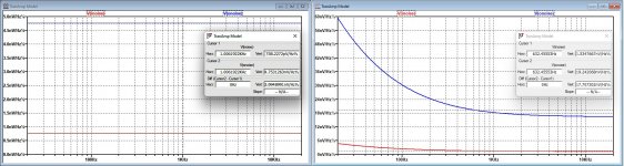
See both models below, one is only composed of resistors and is 100% exact, with only Ro to be estimated, but not having a great impact.
That both models, active and passive give the same RTI may not be a surprise, but when calculating the Exact resistor model by hand, gives again the same noise figure.
So when you know what you are doing, LTSpice is quite helpful, other than calculating THD and IMD figures which mostly results in wishful thinking.
But when measuring the real thing you will never achieve these theoretical figures, so better as simmed is an utopia, but within +5% is what I mostly see.
Just recently I simmed the Wayne Kirkwood's preamp, sim versus measurement was again within +5%.
The other thing I agree is that calculating figures without having a reason doesn't make too much sense.
What does it bring when a bare Diff amp alone has an RTI below 300pV/rtHz when in later stages this noise is ruined.
Only when the goal is that at the point where the final output is produces, RTI should not be more then X% of the Diff amp's RTI alone, then it makes sense to look at the RTI.
When however RTI@1Khz as seen after the Riaa stage is way above the 1nV/rtHz, then in my opinion putting so much effort in a low noise diff amp is almost a waste of energy.
Hans
I agree that using LTSpice for noise calculations can be tricky and needs enough background know how.
But when the model is right, LTSpice does really a perfect job that conforms exactly to manual calculation.
See both models below, one is only composed of resistors and is 100% exact, with only Ro to be estimated, but not having a great impact.
That both models, active and passive give the same RTI may not be a surprise, but when calculating the Exact resistor model by hand, gives again the same noise figure.
So when you know what you are doing, LTSpice is quite helpful, other than calculating THD and IMD figures which mostly results in wishful thinking.
But when measuring the real thing you will never achieve these theoretical figures, so better as simmed is an utopia, but within +5% is what I mostly see.
Just recently I simmed the Wayne Kirkwood's preamp, sim versus measurement was again within +5%.
The other thing I agree is that calculating figures without having a reason doesn't make too much sense.
What does it bring when a bare Diff amp alone has an RTI below 300pV/rtHz when in later stages this noise is ruined.
Only when the goal is that at the point where the final output is produces, RTI should not be more then X% of the Diff amp's RTI alone, then it makes sense to look at the RTI.
When however RTI@1Khz as seen after the Riaa stage is way above the 1nV/rtHz, then in my opinion putting so much effort in a low noise diff amp is almost a waste of energy.
Hans
Attachments

Are we all in agreement that with a 22 Ohm resistor across the TranBal inputs, the QA401 spot noise reading of -121 to -122 dBV is reality and the QA401 is not giving a bad answer?
Can we agree that with this info and the exact gains per stage, we can calculate accurately the total RTI noise (amp plus 22 Ohm resistor)?
Can we agree if we subtract the noise current of the 22 Ohm RMS style we get the total amp only input referred current noise and from this can state a notional noise voltage (yes, I am choosing my words carefully to avoid confusion)?
Finally, if that total noise after subtraction is then at or very close to the sim’d value of 292pV with the sim’d inputs shorted, it confirms the noise performance of the amplifier?
Optimising the signal chain gains for lower noise is a separate subject. We should not even attempt that without establishing the veracity of the measurement methodology.
Given that modelling a system and then measuring the resultant performance of a practical case is de riguer in many areas of science and engineering (aerospace, biology, electronics are a few examples), I fail to see what the fuss is about on my methodology. I’ve done exactly what is considered normal practice.
Rather than hurl insults or claim the TranBal does not meet spec, perhaps someone would calculate the noise on the input of the TIS given the model output of 11.5 nV. I have shown my calculations and reasoning - repeated 2 or 3 times above. Explain why it is wrong. I’ve made it clear why Syn08’s treatment is incorrect.
I really don’t want poison this thread with anymore bs. If we cannot have gentlemanly discussion, please leave the thread.
Hans, indeed Spice is excellent for determining the equivalent Johnson noise. It replaces the real part of any reactance with it's equivalent thermal noise source, then does the math. However, there are several noise mechanisms that are by default poorly or not at all included:
- Leakage current noises (such as in electrolytic capacitors)
- Excess noise. Excess noise models in passive components models are not included, while for active components they are crude and anyway expected in the device models.
- Noise corner frequencies, once again expected in the device models, which rarely include them.
- Large signal noise injection mechanisms are not included, all noise models are considered linear, and linear analysis is used to determine the noise budget.
- Home
- Source & Line
- Analogue Source
- Low noise Balanced MC Pre