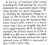
Sorry, doesn’t compile, I have no idea what you are doing there. How are you translating from the time domain (output noise voltage) to the frequency domain (noise spectra) without Mr. Fourier’s help.Just to explain, this is not an FFT, but an analog analyzer with a 5th order bandpass filter. Divide by the filter factor -- as described by Jung in his 1995 articles "Regulators for High Performance Audio".
Last edited:
Jack and how did you calculate from RTO to RTI, in other words, how did you know the gain.
Hans
Hans
See from WJ. As a sanity test (again) I used Sam's amplifier with 64, 390 and 1k resistors to check the filter factor (SQRT 0.2316). The AP noise floor is a bit lower in the Analog mode, compared to the DSP mode. There is an AP-BASIC macro ("FFT Scaling for Noise") which corrects FFT's for windowing, bin size, but I prefer Analog.Sorry, doesn’t compile, I have no idea what you are doing there. How are you translating from the time domain (output noise voltage) to the frequency domain (noise spectra) without Mr. Fourier’s help.
At one time, I used an HP3581a "Wave Analyzer" which has selectable crystal filters for bandwidth. Laborious.
To determine the gain vs frequency, I "stereo sweep" the voltage across the 3.3R resistor (suggested by Bonsai) AND the output, both in balanced mode, dump the data into Excel. Disconnect the generator from the amplifier, turn the generator off, remove the leads from the cookie tin and sweep the output. The gain is very close to (Rc||Zload)/r'e.
Attachments
Same Jung paper describes what you call flat a "bandpass filter" as a constant Q filter sweeping the frequency band of interest, which is actually a Fourier transform method. Since this filter is constant Q, the Fourier transform result has to be corrected for the non-constant bandwidth across the spectra, otherwise the measured noise will increase by 3dB/decade. I know nothing about the System One AP you are using, but I would assume it does this automatically.
Why are you not feeding the output to the Groner amp followed by a standard noise spectrum analysis (I am not aware of any spectrum analyzer, even from the 60's, without this capability) is beyond my understanding. Not to mention that any sound card with the free ARTA will do the same. Also, the sanity test I suggested is not to check the filter factor, but to check the noise measurement consistency, since adding a resistor to the source changes both the gain and the output noise - but the RTI noise of the amplifier, that can easily be calculated, should stay the same.
IMO, you are needlessly complicating what could be a very straightforward measurement.
P.S. I have no idea about the AP filter Q, but the method used could very well explain why the 60Hz and harmonics are missing - they may not fall into the filter Q bin during the sweep.
Last edited:
I agree with Syn08 that your workfow is rather mysterious.See from WJ. As a sanity test (again) I used Sam's amplifier with 64, 390 and 1k resistors to check the filter factor (SQRT 0.2316). The AP noise floor is a bit lower in the Analog mode, compared to the DSP mode. There is an AP-BASIC macro ("FFT Scaling for Noise") which corrects FFT's for windowing, bin size, but I prefer Analog.
At one time, I used an HP3581a "Wave Analyzer" which has selectable crystal filters for bandwidth. Laborious.
To determine the gain vs frequency, I "stereo sweep" the voltage across the 3.3R resistor (suggested by Bonsai) AND the output, both in balanced mode, dump the data into Excel. Disconnect the generator from the amplifier, turn the generator off, remove the leads from the cookie tin and sweep the output. The gain is very close to (Rc||Zload)/r'e.
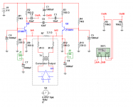
A functional circuit diagram would be very helpful to understand what you did with more details of your calculations.
Hans
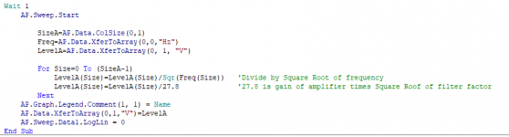
Measure the gain, short input to ground (in this case with 1,000uF capacitors), run macro noise.apb. For lowest environmental noise, cables from signal generator are removed and amplifier is placed in cookie tin and allowed to settle. (The tin itself is connected to the analyzer chassis ground a la Morrison "Grounding and Shielding Techniques in Instrumentation").
Whether you run it with FFT (adjusting for FFT length and window with the AP FFT Scaling macro), the DSP analyzer, or Analog Analyzer and macro, or dump the data into Excel, the results are quite comparable.
This is getting OT. I am open to suggestion, but perhaps in another thread.
Whether you run it with FFT (adjusting for FFT length and window with the AP FFT Scaling macro), the DSP analyzer, or Analog Analyzer and macro, or dump the data into Excel, the results are quite comparable.
This is getting OT. I am open to suggestion, but perhaps in another thread.
Attachments
The OPA2188 is very quiet - please see my X-Altra MC/MM noise results - c. 232 pV/rt Hz 1 kHz spot noise and pretty ok everywhere across the audio band.
Some of the older chopper amps were very noisy and I believe these would be an issue - the 2188 and its cousins are spectacularly good for what they do. In run my OPA2188 off +-15V rails - I don't know if running choppers off lower rails is a factor.
Re your noise graphs, I am not familiar with the AP set-up (although I must confess I lie in bed at night and lust after one 🙂 ). Seems to me if you are accounting for the TranBal gain, then your results are pretty good. Maybe the other guys want to comment.
(I'd appreciate it if you would leave your discussion here - I am quite happy with it since it brings some interesting stuff to the table that we can discuss hopefully in a constructive manner)
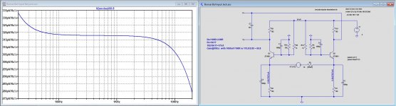
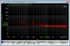
This is what you can get best case with your setup, a spot noise RTI of 318nV/rtHz at 1Khz with both emitters shortened by 1000uF caps.Measure the gain, short input to ground (in this case with 1,000uF capacitors), run macro noise.apb. For lowest environmental noise, cables from signal generator are removed and amplifier is placed in cookie tin and allowed to settle. (The tin itself is connected to the analyzer chassis ground a la Morrison "Grounding and Shielding Techniques in Instrumentation").
Whether you run it with FFT (adjusting for FFT length and window with the AP FFT Scaling macro), the DSP analyzer, or Analog Analyzer and macro, or dump the data into Excel, the results are quite comparable.
This is getting OT. I am open to suggestion, but perhaps in another thread.
Attachments
Can you plot Vinoise Hans? Much quicker and easier (I use Vonoise for PSU's etc, but Vinoise for amplifiers)
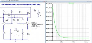
Jack, here' s my sim of your set-up. I'm getting a similar result to Hans using a more conventional measurement set-up (emitter resistors are not shorted out and looking at Vinoise). Can you confirm what the voltage drop across the emitter resistors since this will tell us the emitter current and therefore re' a major noise contributor. The other thing I note is that you have your gain set at c.28. Whether I use 50 Ohm or 182 Ohm collector load resistors, I get the same input referred noise figure. So one thing you might want to check is if you have the correct TranBal gain keyed into in your set-up.
Note: In the design that I am awaiting the first PCB for, the emitter currents are running at about 15mA c.f. a 10V rail to the front end and not 6V as you have shown so the 1kHz spot noise is in the region of 275pV/rt Hz, rather than the higher number Hans and I are getting with this sim.
Note: In the design that I am awaiting the first PCB for, the emitter currents are running at about 15mA c.f. a 10V rail to the front end and not 6V as you have shown so the 1kHz spot noise is in the region of 275pV/rt Hz, rather than the higher number Hans and I are getting with this sim.
Attachments
Last edited:
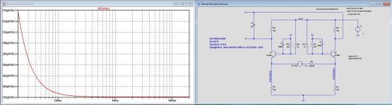
Vinoise can’t be plotted because the cart is shortened by the two 1000uF caps, so this is the only way, just following Jacks complex workflow.Can you plot Vinoise Hans? Much quicker and easier (I use Vonoise for PSU's etc, but Vinoise for amplifiers)
But I could remove these caps and use a very low Cart resistance like 0.01R.
In that case Vinoise can be plotted, result at 1Khz is the same.
Hans
Attachments
Just a suggestion -- you might want to adjust the models of the ZTX851 for some subtle differences, i.e. ZTX851A and ZTX851B such that there is a potential difference between the emitter and emitter resistor junction such that current flows through the cartridge to observe the current noise.
It’s a Different mechanism Jack and not to do with bias or offset flowing between the inputs. In this case, since Rsource is very low, the noise current component will only be a small part of the total noise ie Vnoise (thermal aka Johnson noise) dominates
The emitter intrinsic resistance is extremely small, usually less than 0.1ohm. It can safely be ignored, for all practical purposes.
Within limits, DC offset is not a factor in the noise budget of a differential pair. Whatever the offset, the sum of the input bias (base) currents is constant, and since these are uncorrelated noise sources they add up anyway.
Within limits, DC offset is not a factor in the noise budget of a differential pair. Whatever the offset, the sum of the input bias (base) currents is constant, and since these are uncorrelated noise sources they add up anyway.
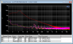
Best thing is to go back and check the system gains. If the noise calculation in the AP is assuming the wrong gain, you will get erroneous results. With LTspice you don’t have this problem of course because the gain is accurately calculated and always correct. I’ve found the LTspice noise projections remarkably accurate. Just use a few resistors - say 10, 100 and 1 k - to cal your system.I don't even want to show this. I ran the noise test with a Denon DL-103. I ran it again. The chart is output noise which is much too low as the DL-103 impedance is 40 Ohms. Amplifier gain is 56.4.
- Home
- Source & Line
- Analogue Source
- Low noise Balanced MC Pre