I'm so excited to get this amplifier together. My daughter and I are doing this as a daddy daughter project, it's her first kit and her first time soldering anything. We just got done stuffing and soldiering all the PCBs today after working on them little by little the past week. The next stage is assembling the case and mounting. What a cool project to be part of and I'm so thankful for Mr. Pass for bringing us this rare opportunity.
Since I know everyone here loves tinkering with things, I'm curious what little flourishes you guys have been adding to your own amps, if any. I'm building my just as it came to really enjoy what was designed first then we will see what ends up happening 🙂
Since I know everyone here loves tinkering with things, I'm curious what little flourishes you guys have been adding to your own amps, if any. I'm building my just as it came to really enjoy what was designed first then we will see what ends up happening 🙂
It is great to hear your daughter is involved in the build. My only advice is about the front panel. In the build guide for the P channel 6L6 installs it early in the build. I ignored this and left it for last. It was very difficult to get it installed last. My only change was to use a different socket head fastener to bolt the output stage to the heat sink. Allowed for a little more torque for better contact.
JZatopa,
Great to know that you and your daughter are building the amp together.
Good luck with the build! Hope you can get the amplifier up and running very soon.
Great to know that you and your daughter are building the amp together.
Good luck with the build! Hope you can get the amplifier up and running very soon.
I installed nice solid alu-feets with built-in rubber O-rings.
I did not connect the power switch at the back panel for less wiring and maybe troubles later with the tiny switch. I power everything from a central place. As I want as little light to look into when listening I did not install the LED at the front but just at the input power board. Then I can just look down into the amp if in doubt if it has power.
I did not connect the power switch at the back panel for less wiring and maybe troubles later with the tiny switch. I power everything from a central place. As I want as little light to look into when listening I did not install the LED at the front but just at the input power board. Then I can just look down into the amp if in doubt if it has power.
Taller feet to increase airflow under the chassis.
With 28 d. Celsius ambient, temperature inside the enclosure between the two amp boards was 40d. near the bottom, 42 d. near the top. That’s with the standard feet and with top lead on (with top lead off , temp was two degrees lower).
Raising the feet height by adding 15mm blocks, internal temp fell by three degrees.
George
Hi everybody.
I just start building mine.
I've got two 1000µF/35V Silmic II. Is it ok for C2 ?
I also have two 2200µF/63V BlackGate FK. Could I use them with the Rubycon output cap ?
Thanks
Damien
I just start building mine.
I've got two 1000µF/35V Silmic II. Is it ok for C2 ?
I also have two 2200µF/63V BlackGate FK. Could I use them with the Rubycon output cap ?
Thanks
Damien
Well I'm at the point I'm starting to wire up the amp and I have two questions.
1. Is the thicker gauge wire copper or aluminum? I have some pre-tinned copper wire I've used before that was like this but I just wanted to confirm this isn't aluminum wire.
2. Do I only need to find a DPDT if I have a turn on/off thump?
1. Is the thicker gauge wire copper or aluminum? I have some pre-tinned copper wire I've used before that was like this but I just wanted to confirm this isn't aluminum wire.
2. Do I only need to find a DPDT if I have a turn on/off thump?
Well I'm at the point I'm starting to wire up the amp and I have two questions.
1. Is the thicker gauge wire copper or aluminum? I have some pre-tinned copper wire I've used before that was like this but I just wanted to confirm this isn't aluminum wire.
2. Do I only need to find a DPDT if I have a turn on/off thump?
It's tin coated copper i believe.
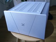
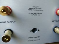
I am happy to report that #116 is alive! It was pure joy to put together such special kit. I feel so blessed 😱
Attachments

Anyone having good success with any of the DIY Audio store preamps with the N-Channel? Using a passive now with great success, but would like to try my first preamp build. Also, looking at the SRPP Glassware kit as well.
The Broskie SRPP sounds nice
Cool. Is it pretty quiet? I know the gain can vary between 9db to 12db depending on the tubes used. I also wonder if his guides are as good (because of my lack of long build experience) as 6L6's and the schematics that Nelson puts out.
Yeah. I felt like it was pretty quiet. It’s without chassis at the moment. I used JJ and Genalax tubes. They both sounded nice to me. Broskie includes a nice little pamphlet with board/kit. It does get into some build specifics, but is more geared towards explaining and optimizing the circuit.
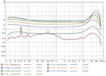
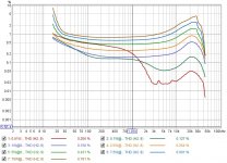
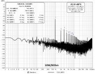
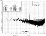
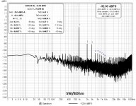
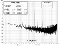
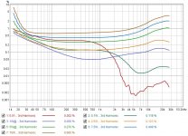
Some measurements showing the distortion profile of my build on 8 Ohm dummy load at discrete power levels ( 0.01W, 0.1W, 1W 2.5W, 5W, 7.5W, 10W)
George
George
Attachments
-
 2nd harmonic.jpg133.4 KB · Views: 116
 -
 THD.jpg145.6 KB · Views: 118
 -
 10W dist spectrum.jpg185.7 KB · Views: 117
 -
 7.5W dist spectrum.jpg185.8 KB · Views: 111
 -
 5W dist spectrum.jpg184.8 KB · Views: 114
 -
 2.5W dist spectrum.jpg185.4 KB · Views: 121
 -
 1W dist spectrum.jpg185.4 KB · Views: 134
 -
 0.1W dist spectrum.jpg185.9 KB · Views: 137
 -
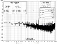 0.01W dist spectrum.jpg189.9 KB · Views: 314
 -
 3rd harmonic.jpg133.7 KB · Views: 106
- Home
- Amplifiers
- Pass Labs
- DIY Sony VFET pt 2 (N-Channel Build)