Hi Mbrennwa,
The specs are 600VA class EI core made of grain oriented silicon steel (GOSS). There is a 0.1mm airgap. The windings are 14 ga copper magnet wire that is bifilar wound to produce 60mH at 10kHz and 0.5ohm DCR. Inductor has nominally linear impedance variation (no spikes or dips) over audio range from 20Hz to 20kHz.
Earlier in this thread there are many companies discussed and some suggested by Daanve and others that are in Europe and USA.
Last edited:
Hi Mbrennwa,
Please see PM.
I have let the amp warm up and stay on all day and the DC offset appears to be very stable within +/10mV once set. When cold it is about 20mV off but after an hour our so settles on the same value. With the SSR speaker protection circuit in place, I feel totally confident that DC offset error is a non issue.
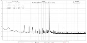
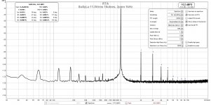
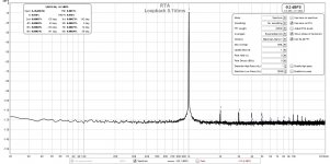
I was noticing some strange artifacts on my FFT measurements using the Focusrite 2i4 so I decided to use a different USB audio interface. I suspect the Focusrite front end somehow got damaged as the distortion looked really bad sometimes and the noise levels high. I switched to a Behringer UM-2 interface and used the provided ASIO interface at 96kHz. The measurements look cleaner now. The source is still the Akitika 2ppm 1kHz oscillator, single ended to balanced buffer is a BTSB Panel v1.2p with OPA1637 balanced line drivers. Dummy load is a 10ohm EBG UXP-300 fan cooled flat thin film power resistor.
Here are the measurements assuming 10ohms is close enough to 8ohms.
2.83Vrms (1w into 8ohms), THD=0.0071%:

4.0Vrms (2w into 8ohms), THD=0.0099%:

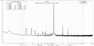
5.6Vrms (4w into 8ohms), THD=0.014%:

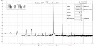
8.0Vrms (8w into 8ohms), THD=0.023% :

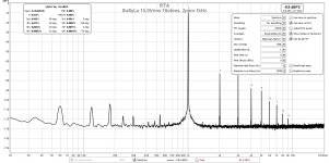
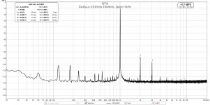
11.0Vrms (15w into 8ohms), THD=0.039%:

15.0Vrms (28w into 8ohms), THD=0.088%:

20.0Vrms (50w into 8ohms), THD=0.54%:

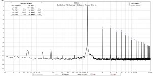
28.3Vrms (100w into 8ohms), THD=1.4%:

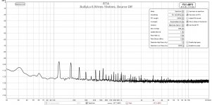
0.0Vrms - background baseline noise with source OFF:

The predicted THD at 100w matches the predicted 1.47% value from LTSpice. The THD at lower outputs are in general high, however the measured distortion appears to be 2nd harmonic dominant at lower powers due to mismatch of devices or components. This increases the THD slightly, but well worth the trade, IMO. The dominant 2nd harmonic profile appears to be good until about 25-28Wrms.
Here are the measurements assuming 10ohms is close enough to 8ohms.
2.83Vrms (1w into 8ohms), THD=0.0071%:
4.0Vrms (2w into 8ohms), THD=0.0099%:
5.6Vrms (4w into 8ohms), THD=0.014%:
8.0Vrms (8w into 8ohms), THD=0.023% :
11.0Vrms (15w into 8ohms), THD=0.039%:
15.0Vrms (28w into 8ohms), THD=0.088%:
20.0Vrms (50w into 8ohms), THD=0.54%:
28.3Vrms (100w into 8ohms), THD=1.4%:
0.0Vrms - background baseline noise with source OFF:
The predicted THD at 100w matches the predicted 1.47% value from LTSpice. The THD at lower outputs are in general high, however the measured distortion appears to be 2nd harmonic dominant at lower powers due to mismatch of devices or components. This increases the THD slightly, but well worth the trade, IMO. The dominant 2nd harmonic profile appears to be good until about 25-28Wrms.
Attachments
-
 SuperNova-2.83Vrms-10ohms-FFT.jpg201.5 KB · Views: 575
 -
 SuperNova-0.0Vrms-10ohms-FFT.jpg213.6 KB · Views: 1,467
 -
 SuperNova-28.3Vrms-10ohms-FFT.jpg204.1 KB · Views: 548
 -
 SuperNova-20.0Vrms-10ohms-FFT.jpg202.6 KB · Views: 549
 -
 SuperNova-15.0Vrms-10ohms-FFT.jpg227.6 KB · Views: 1,430
 -
 SuperNova-11.0Vrms-10ohms-FFT.jpg226.4 KB · Views: 554
 -
 SuperNova-8.0Vrms-10ohms-FFT.jpg227.1 KB · Views: 1,475
 -
 SuperNova-5.6Vrms-10ohms-FFT.jpg197.2 KB · Views: 566
 -
 SuperNova-4.0Vrms-10ohms-FFT.jpg197.8 KB · Views: 560
Last edited:
It would be interesting to see the residual harmonics of the analyzer. Can you show the oscillator directly into the analyzer?
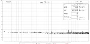
Here is loopback test with Akitika 2ppm oscillator input directly into UM-2 input using a TS RCA plug adapter (shorts sleeve and ring or pins1 and 3 on XLR) so single ended input to balanced jack. Looks like limit of UM-2 is about 0.001% THD, which is fine for this purpose. The UM-2 appears to have some self noise near 1kHz at a low level, and its harmomics.
Loopback with 0.10Vrms ampitude gives THD limit of 0.0013%:

Self Noise (oscillator turned off):

Performance wise, not as good as Focusrite 2i4 (when it was working well), but price was only $30 vs $150, so not too bad for most casual DIY uses.
Loopback with 0.10Vrms ampitude gives THD limit of 0.0013%:
Self Noise (oscillator turned off):
Performance wise, not as good as Focusrite 2i4 (when it was working well), but price was only $30 vs $150, so not too bad for most casual DIY uses.
Attachments
Well those are some informative graphs.
It seems that the SuSyLu prototype has a noisy power supply. Not horrible, but some room for improvement.
It seems that the SuSyLu prototype has a noisy power supply. Not horrible, but some room for improvement.
Either that, or there is still a (s.am ground loop somewhere. Maybe it's in the way the test equipment is hooked up to the amp. I am not worried about the residual 120 Hz peak though.
I was simply wondering if the low distortion numbers of the amp are accurate, or if they are limited by the test equipment.
I was simply wondering if the low distortion numbers of the amp are accurate, or if they are limited by the test equipment.
Well those are some informative graphs.
It seems that the SuSyLu prototype has a noisy power supply. Not horrible, but some room for improvement.
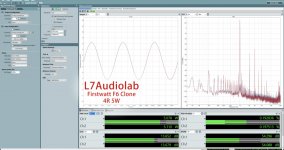
That’s actually very good for a simple CRCRC linear PSU on a Class A amp without a cap multiplier. Have you seen what a typical FFT from usual 25w Class A amp with only CRC (usual 22,000uF // 0.47Rx4 // 22,000uF)? The 60Hz/120Hz peak is about -70to -80dB if I recall.
Here is one from an F6 measured by ASR:
Attachments
Last edited:
The specs are 600VA class EI core made of grain oriented silicon steel (GOSS). There is a 0.1mm airgap.
Just trying to learn and understand the background if these specs:
- Why is it 600 VA?
- How did you determine the size of the airgap?
The 600VA size is to make sure the steel core and windings have enough magnetic energy storage (the inductor provides the opposite swing and we want to make sure its reserves are big enough to handle multiple bass transients). It’s a 100w amp (80Vpp in BTL mode) and each leg needs to make 40Vpp swings from a 28v dc rail. That’s 12v extra that needs to come from the inductor. A smaller value might work, I just sized it big to make sure it never has an issue with magnetic flux depletion.
0.1mm air gap comes from recommendations by others who have designed these types of inductors before. EI cores actually have some air gap built in. But adding a 0.1mm shim ensures this spec. This is to prevent DC saturation in case the two legs don’t have perfect balance.
0.1mm air gap comes from recommendations by others who have designed these types of inductors before. EI cores actually have some air gap built in. But adding a 0.1mm shim ensures this spec. This is to prevent DC saturation in case the two legs don’t have perfect balance.
The 600VA size is to make sure the steel core and windings have enough magnetic energy storage (the inductor provides the opposite swing and we want to make sure its reserves are big enough to handle multiple bass transients). It’s a 100w amp (80Vpp in BTL mode) and each leg needs to make 40Vpp swings from a 28v dc rail. That’s 12v extra that needs to come from the inductor.
600 VA / 12 V = 50 A total, or 25 A from each leg.
That seems like an insanely large current going from the choke to the speaker.
What am I missing?
25A is what you want from a Class AB amp if bass authority is what you need. This amp sounds and feels like a big Class AB amp in the bass department. It’s also got to be able to handle multiple bass excursions in succession without running out of steam. The energy gets depleted with each use and slowly charged back up when there are no deep excursions.
Let me ask you why do we use 400VA toroidal cores on a 25w Class A amp? They run about 75W dissipation per channel or 150W stereo. Seems like a 200VA trafo should be fine - but it’s not. You don’t want to operate a transformer more than 50% of its rated power. It stresses it and the voltage sags.
You could try smaller VA cores - maybe it will work fine. I know that the MOTs I used were rated 10A and weighed 8.5lbs. This 600VA dual weighs about 11lbs.
If we think about it as energy storage from the last cap on the PSU vs energy storage in the inductor. We want both to be about the same so that the “push” is about the same as the “pull.” It might be overly simplistic but let’s look at the equation for energy storage in a capacitor. Let’s say the cap needs to provide 12v of swing and it’s got 15,000uF (that’s what is there now). E = 1/2 x C x V^2 is energy stored in a cap in Joules. We get 1.08 Joules.
For the inductor, the energy is given by E = 1/2 x L x I^2. At 50Hz I think the inductance was about 200mH or 0.2H and the DC current charging it is 3A. The stored energy inductor as about 0.9 Joules.
About balanced on both sides. I guess if you can get 200mH and 0.5ohm DCR at 50Hz from a smaller VA core, it should be fine. I think it’s hard to physically wind bifilar 14ga wire to achieve that on a smaller core would be my concern.
Last edited:
Ok, I see, makes sense (although my thoughts on the 400 VA PSU tranny for a 25 W class-A amp would be along different lines).
My LU1014D and LD1014D parts that I have tested so far tend to be at Vgs = -0.7V to -1.1V at Ids = 3A and Vds = 2.3V.
Looking at the voltages in the schematic of the first post in this thread, a Vgs value of 1.5V would be needed to get a 3A DC idle current running through each winding of the balanced choke (0.5 Ohm DCR per winding).
What's your thought on this? Find a choke with a lower DCR? Look for LU1014D parts with unusually high Vgs?
Last edited:
I think the pot on the cascode can adjust the voltage driving the JFET a tad higher and you will get 3A just fine.
For example, Woofertester matched mine and nominal values are:
Vgs of -0.786v, Vpinch of -1.204v, gm of 22.6
Vgs of -0.782v, Vpinch of -1.192v, gm of 23.4
Plus, I have used random units from bulk tape, not ever characterized and I can always dial in 3A easily.
For example, Woofertester matched mine and nominal values are:
Vgs of -0.786v, Vpinch of -1.204v, gm of 22.6
Vgs of -0.782v, Vpinch of -1.192v, gm of 23.4
Plus, I have used random units from bulk tape, not ever characterized and I can always dial in 3A easily.
Ok, but that will crank op the drain-source voltage to maybe 4-5 V. At 3 A idle, That's 15 W idle dissipation. Nelson Pass said that the LU1014 should not be running at more than 10 W. How hot can you safely run the LU?
The datasheet says 50w which I think is a bit high. I have run it at 25w before. I have no issue running it at 15w. Just make sure you have adequate heatsinking.
Alright then. Just to make sure I understand this correctly: the Vda value shown in the schematic in the first post is 3.9 V. With the 1.5 V across the choke, the LU1014D drain-source voltage in the SPICE sim would be 3.9 V - 1.5 V = 2.4 V.
What values do you observe in your real-world build with your LUs as described in your post #216?
What values do you observe in your real-world build with your LUs as described in your post #216?
It follows the LTSpice sim for LuFo very closely. SuSyLu is just two parallel LuFos.
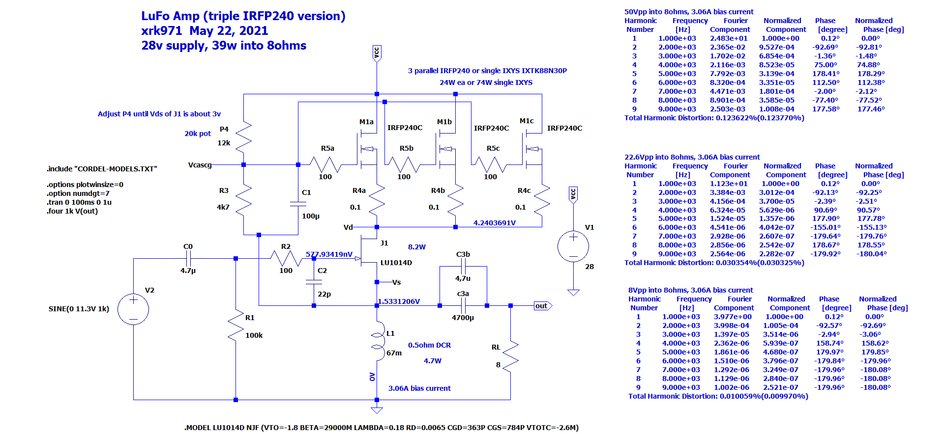
So Vds would be about 4.2v-1.5v or 2.7v or thereabouts.
So Vds would be about 4.2v-1.5v or 2.7v or thereabouts.
- Home
- Amplifiers
- Pass Labs
- SuSyLu Where Are You?