When only one leg of the SuSyLu is used (LuFo amp) with an active bridge, CRC, and capacitance multiplier PSU - this is what the FFT looks like on the left of 1kHz. The SNR is of order 115dB. I have yet to see a published FFT of a linear PSU class A amp with simple CRC achieve anything like this.
The 60Hz peak here is equivalent to about 14uV rms mains noise.
That's good enough.
With correct grounding and layout you should get at least the same results with SuSyLu because there will some noise cancelling.
A single supply (SLB or whatever) is a good starting point IMO.
Last edited:
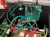
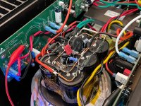
Once I realized that the ground loop was caused by splitting the front end preamplifier boards into each side, I knew that the OPA454 boards need a low impedance common ground in order for the balanced input to work properly. So I made a ground strap using two 16 ga high strand count silicone RC drone / race car wire to connect the GND bolt of each of the daughterboard modules together. This hopefully simulates the situation as if they were both on the same PCB with same ground plane. It works! The hum is gone. The amp measures 0.2mV rms at the speaker output. This was same as the level I had before I connected the audio input. There is only noise audible if ears are closer than 4 in from speaker cone. The noise that is there is probably residual ripple from simple CRC PSU under Class A load.
Arrows show ground strap points. Wires from balanced TRS jack is now coaxial RG174 (although that by itself did not help). I tried not connecting the ground from the TRS jack to the amp boards. That did not help.

Here is amp with Fluke 101 connected to outputs at speaker out showing 0.2mV rms.

Arrows show ground strap points. Wires from balanced TRS jack is now coaxial RG174 (although that by itself did not help). I tried not connecting the ground from the TRS jack to the amp boards. That did not help.
Here is amp with Fluke 101 connected to outputs at speaker out showing 0.2mV rms.
Attachments
Great job! Looks like a dedicated board design for the SuSyLu would be good (single front end, dual outputs for separate mounting on heatsinks). You could also skip the DC blocking caps, which are not needed anymore.
Maybe that did not help with the hum, but it was still a step in the right direction. The "ground" of the balanced wire connector must connect to the chassis, not to the audio circuitry. Take a look at this for more information.
I tried not connecting the ground from the TRS jack to the amp boards. That did not help.
Maybe that did not help with the hum, but it was still a step in the right direction. The "ground" of the balanced wire connector must connect to the chassis, not to the audio circuitry. Take a look at this for more information.
Hi Guys,
Thanks for the links on balanced line cable grounding. Let me try removing the shield from signal ground and connect it to just chassis ground. I think I did this before and it had the same performance. But had hum if you disconnected only one leg of the audio input to one side (normal). Whereas if the shield was connected to signal ground, it did not. But the truth is, if we use XLR, both will be connected at the same time and we should not be “hot plugging” audio inputs on a live amp in any event.
Thanks for the links on balanced line cable grounding. Let me try removing the shield from signal ground and connect it to just chassis ground. I think I did this before and it had the same performance. But had hum if you disconnected only one leg of the audio input to one side (normal). Whereas if the shield was connected to signal ground, it did not. But the truth is, if we use XLR, both will be connected at the same time and we should not be “hot plugging” audio inputs on a live amp in any event.
,,,removing the shield from signal ground and connect it to just chassis ground. ... But had hum if you disconnected only one leg of the audio input to one side (normal). Whereas if the shield was connected to signal ground, it did not.
If you disconnect either the HOT or the COLD audio connection, the balanced audio connection is incomplete, because the audio signal is HOT-COLD. I am not surprised this causes hum, because the part of the audio signal on the connected wire lost it's reference (the other wire). It's a similar situation like using a single ended connection with the GND disconnected, so the audio signal is missing its reference.
If you have the the shield (wrongly) connected to audio GND, you may (accidentally) introduce some pseudo reference for the one audio wire that is still connected, possibly via some "ground loop breaker" connection between the chassis and the audio GND of the audio source. This will reduce the hum.
I have tested the audio input connections without the TRS shield connected to the amp GND input and it did not change anything. In fact, disconnecting the audio cable completely had the same 0.2mV signal as connecting the balanced TRS source. Pressing my ear to the speaker cone it sounded the same.
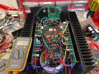
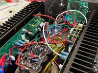
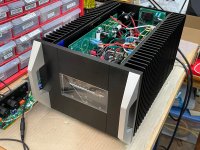
I tried adding an additonal RC stage on the PSU for a CRCRC (same 0.33R in parallel and 15,000uF 50v caps). The measured ripple went 100mV to 50mV. However, the measured noise at the output remains at 0.2mV. The amp voltage did drop to 29.1v now so the heat dissipated out of the heatsinks will be less as it is radiating off the power resistors on the CRCRC now.
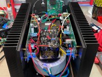
Here is the amp with the CRCRC:

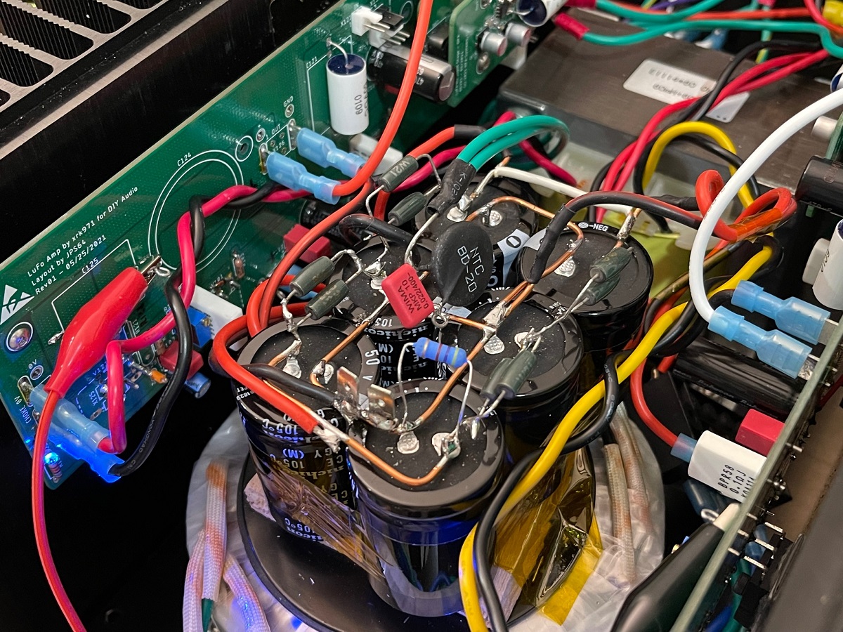
Here is a closeup of the CRCRC:
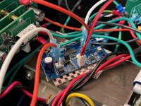
I also got a chance to install my solid state relay speaker DC protection circuit. This is the Gen 2 design that has an optically isolated speaker DC sense circuit so that it can be used with BTL amp where both speaker connections are live. it is powered off the 29v rail. There is an on board voltage regulator that makes 15v for the SSR to work properly. Of course, it is compeltely transparent and adds no noise or distortion (as shown in earlier measurements). I do feel that the amp is much safer now knowing that it cannot harm my speakers even though it is DC coupled.

Here is a closeup of the SSR:

In the meantime, I am just going to let it play music for a while to burn in and then case it up tomorrow with bolts and all.
I tried adding an additonal RC stage on the PSU for a CRCRC (same 0.33R in parallel and 15,000uF 50v caps). The measured ripple went 100mV to 50mV. However, the measured noise at the output remains at 0.2mV. The amp voltage did drop to 29.1v now so the heat dissipated out of the heatsinks will be less as it is radiating off the power resistors on the CRCRC now.
Here is the amp with the CRCRC:
Here is a closeup of the CRCRC:
I also got a chance to install my solid state relay speaker DC protection circuit. This is the Gen 2 design that has an optically isolated speaker DC sense circuit so that it can be used with BTL amp where both speaker connections are live. it is powered off the 29v rail. There is an on board voltage regulator that makes 15v for the SSR to work properly. Of course, it is compeltely transparent and adds no noise or distortion (as shown in earlier measurements). I do feel that the amp is much safer now knowing that it cannot harm my speakers even though it is DC coupled.
Here is a closeup of the SSR:
In the meantime, I am just going to let it play music for a while to burn in and then case it up tomorrow with bolts and all.
Attachments
Last edited:
Hi Nicoch58,
What are your referring to? EC MC1?
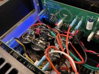
I am using 15,000uF 50v caps rated for 8A ripple current. In a CRC with 0.2ohm R, at a load of 5A this was simulated to show acceptable ripple current spec. The simulation showed 4A rms ripple current and so I spec’d the caps at 2x the predicted value. Here I am running 3A per bank and R is 0.165ohm. The first cap is the one taking the brunt of the ripple.
I am measuring 100mV ripple voltage after the first CRC and 50mV ripple voltage after the second one.
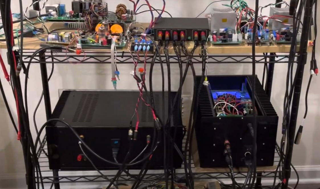
The SuSyLu is buttoned up (no top lid) and noise is still the same at 0.2mV rms. I moved to my main rig and connected to a real DAC and preamp for the first time. ESS9038 KTB1 and my own hybrid ECC88/SS preamp designed by Jhofland and a SE to Bal BTSB buffer also designed by Jfofland. The sound into my 10F/RS225 speakers is amazing. It really is a superb sounding amp! Wonderful and engaging. Wants to make me hear my record collection over again.
I think for the purposes of DIY, the use of the LuFo boards as I have them with a ground strap is perfectly acceptable. I won’t be making a unified input stage board. I’ll make the necessary updates to the LuFo board so it can work as a standalone SE camp coupled amp or as a pair DC coupled balanced amp like SuSyLu.
The performance as is is already more than acceptable. It’s quite outstanding and sounds breathtaking.
What are your referring to? EC MC1?
I am using 15,000uF 50v caps rated for 8A ripple current. In a CRC with 0.2ohm R, at a load of 5A this was simulated to show acceptable ripple current spec. The simulation showed 4A rms ripple current and so I spec’d the caps at 2x the predicted value. Here I am running 3A per bank and R is 0.165ohm. The first cap is the one taking the brunt of the ripple.
I am measuring 100mV ripple voltage after the first CRC and 50mV ripple voltage after the second one.
The SuSyLu is buttoned up (no top lid) and noise is still the same at 0.2mV rms. I moved to my main rig and connected to a real DAC and preamp for the first time. ESS9038 KTB1 and my own hybrid ECC88/SS preamp designed by Jhofland and a SE to Bal BTSB buffer also designed by Jfofland. The sound into my 10F/RS225 speakers is amazing. It really is a superb sounding amp! Wonderful and engaging. Wants to make me hear my record collection over again.
I think for the purposes of DIY, the use of the LuFo boards as I have them with a ground strap is perfectly acceptable. I won’t be making a unified input stage board. I’ll make the necessary updates to the LuFo board so it can work as a standalone SE camp coupled amp or as a pair DC coupled balanced amp like SuSyLu.
The performance as is is already more than acceptable. It’s quite outstanding and sounds breathtaking.
Attachments


Last edited:

Those are 5uF 50v polycarbonate film caps. I got those as a gift from Vunce. They do sound great. I don’t think they are in actual production but you might still be able to find on eBay etc.
Good result X.
Have you abandoned using SLB supplies for SuSyLu?
Have you tried it with an preamp with a differential output, obviating the need for the separate preamp boards?
I guess the stumbling block with building this design is obtaining a suitable inductor.
Have you abandoned using SLB supplies for SuSyLu?
Have you tried it with an preamp with a differential output, obviating the need for the separate preamp boards?
I guess the stumbling block with building this design is obtaining a suitable inductor.
The suitable preamp is indeed available (Aksa Lender) capable of 50v swings. To do balanced drive I would need to use of both channels of the Aksa Lender to get 90Vpp. We have an Aksa Lender daughter board for LuFo in the works already. We could drive SuSyLu from a suitable external preamp but I don’t have a balanced preamp capable of 90Vpp.
Aksa (Hugh Dean) has another preamp (all BJTs) with 250v rail capable of clean SE Class A output 90Vpp swings. But that’s a commercial design.
The current OPA454 solution with up to +/-35V output is actually sounding very nice.
Aksa (Hugh Dean) has another preamp (all BJTs) with 250v rail capable of clean SE Class A output 90Vpp swings. But that’s a commercial design.
The current OPA454 solution with up to +/-35V output is actually sounding very nice.
Last edited:
Some soundclips of various tracks playing in my main system in mono with a real DAC and my TL speakers. Recorded with my phone.
Test of SuSyLu 100W Class A Amp - YouTube
Test of SuSyLu 100W Class A Amp - YouTube
Attachments

Last edited:
Hmm, thinking about it, the circuit of the SuSyLu output stage is so simple it does not really need a PCB at all. That leaves the questions for a suitable front end. I'd be interested to see some ideas:
I am sure there are some nice designs out there! Ideas, suggestions?
- Balanced input
- Balanced output to the SuSyLu output stage
- Capable for 80 Vpp output or so
- All on a single board to avoid GND issues
- Discrete circuit (no opamp chips please)
I am sure there are some nice designs out there! Ideas, suggestions?
Hmm, thinking about it, the circuit of the SuSyLu output stage is so simple it does not really need a PCB at all. That leaves the questions for a suitable front end. I'd be interested to see some ideas:
- Balanced input
- Balanced output to the SuSyLu output stage
- Capable for 80 Vpp output or so
- All on a single board to avoid GND issues
- Discrete circuit (no opamp chips please)
I am sure there are some nice designs out there! Ideas, suggestions?
Certainly a pair of E88CC tubes with 250v B+ could make a fine balanced buffer. I am using one at 90Vpp B+ but it’s driving an opamp output stage:
There are the M2X format front end boards, many of which are capable of 40Vpp to 55vpp output each and as a pair in balanced, can drive even 80vpp to 110vpp. These include Melbourne, the previously mentioned Aksa Lender, and the Pass ACP+, and probably WBA18 could be modified to do this as well.
Yes, I know. You wrote that you might look into options to make it available for others, so I was wondering if there were any news.
What are the exact specs / requirements?
Which company will be able to make these chokes?
What are the exact specs / requirements?
Which company will be able to make these chokes?
- Home
- Amplifiers
- Pass Labs
- SuSyLu Where Are You?