Interesting. I went through my stash of LUs and picked one with a similar Vgs spec as yours (Vgs = -0.806 V @ 2.4 Vds and 1.5 A Ids, same as woofertester test conditions). Let's say my LU is about the same as yours.
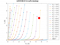
Now take a look at the curves in the attachment:
Biasing this particular LU at 3 A with Vgs = -1.5 V would require a drain-source voltage of about 8 V or so. That would be a dissipation of 3 A x 8 V = 24 W, which is too much. Also, this bias point would not be in a nice/linear range of the curves (data not shown in the diagram, because the current would have exceeded the 5 A limit set during curve tracing).
Either I am deeply confused, or something is not right. What do you think?
Now take a look at the curves in the attachment:
- The Vgs curves are spaced at -0.1 V increments, starting at Vgs = 0.0 V
- The black dot indicates the woofertester test conditions (2.4 V / 1.5 A), which is very close to the -0.8 Vgs curve
- The red dot shows the bias conditions as indicated in your LuFo schematic: 3 A / 2.71 V
Biasing this particular LU at 3 A with Vgs = -1.5 V would require a drain-source voltage of about 8 V or so. That would be a dissipation of 3 A x 8 V = 24 W, which is too much. Also, this bias point would not be in a nice/linear range of the curves (data not shown in the diagram, because the current would have exceeded the 5 A limit set during curve tracing).
Either I am deeply confused, or something is not right. What do you think?
Attachments

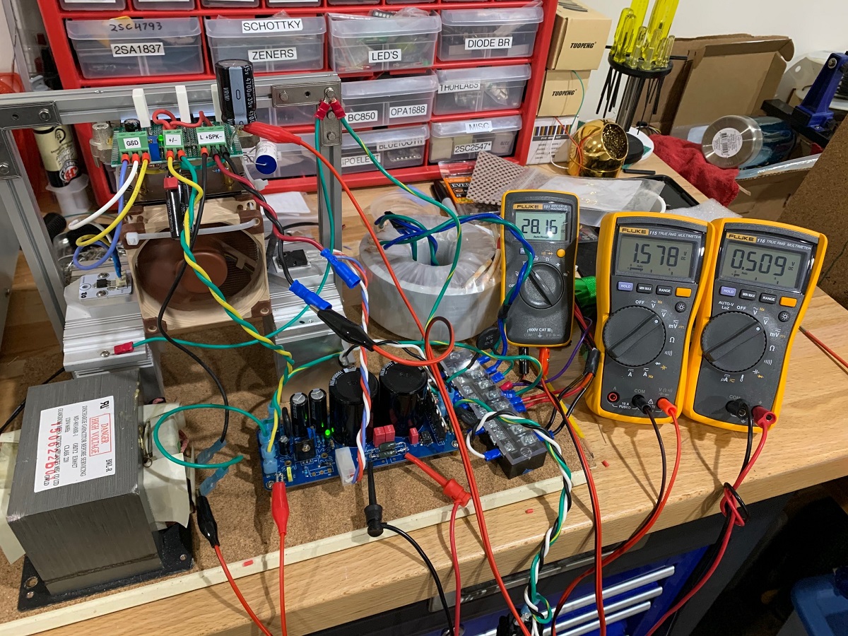
I think the above assumes you run the LU without anything above throttling the current. Sort of an open loop Idss type test. I don’t know what to tell you but LU1014 definitely wasn’t running at 7 or 8v! The DC set points matched the simulation perfectly IF one adjusts the trim pot on the cascode to set the voltage at the source of the JFET to be 1.5v. This gives 3A current and the proper Vds. I don’t have a photo showing the JFET drain voltage, but trust me, it was around 4.x v and it wasn’t 8v. Here is a typical test photo. The two DMMs showing 1.5v are the source voltages for each leg. The 0.5v is the voltage across 4x parallel 0.33R resistors in the CRC of the PSU which gives 6A total or 3.0A per leg. The red DMM shows the supply voltage at 27.6v.

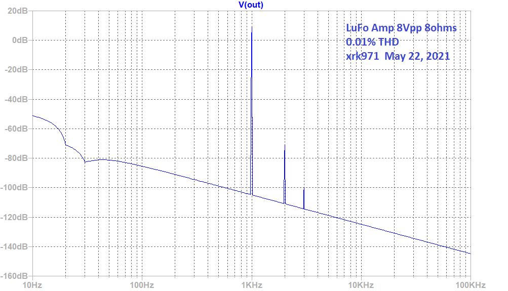
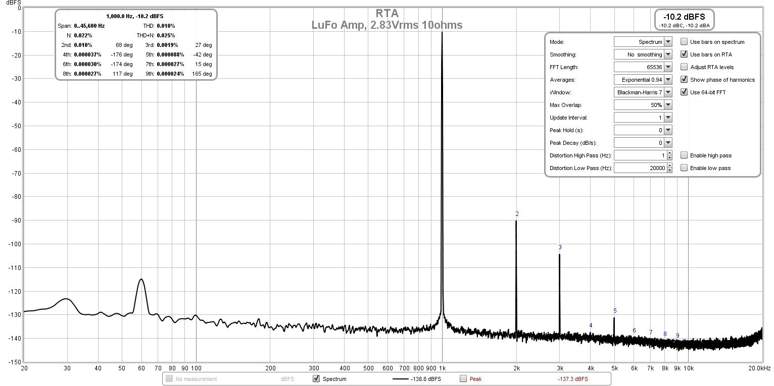
I think if you have more questions about the fundamental topology of the amp, it might be instructive for you to read the LuFo thread. The behavior of the DC setpoints as I said, matches the sim to a T. And the predicted THD and harmonic profile of a single leg (LuFo) matches the measurements perfectly (THD at 2.83v was predicted and measured to be 0.01%). In the first post of that thread:
LuFo (one leg of SuSyLu) predicted harmonic profile and THD for 8Vpp:
Measured harmonic profile and THD of LuFo for 8Vpp:
It’s good to try to understand the amp operation, but I think you have to now just trust that I verified it twice (P2P amp and LuFo PCB proper) and Vunce verified it also (that’s 3 times verified), and you should build it and see for yourself. Make a LuFo first and satisfy your curiosity as to the DC operating setpoints. Then transition the LuFo to a SuSyLu. Nothing lost as it’s all useable as a new monoblock. You just need a balanced inductor for the latter. Use a basic inductor for the LuFo (Hammond, Lundhal, MOT, etc)
I think if you have more questions about the fundamental topology of the amp, it might be instructive for you to read the LuFo thread. The behavior of the DC setpoints as I said, matches the sim to a T. And the predicted THD and harmonic profile of a single leg (LuFo) matches the measurements perfectly (THD at 2.83v was predicted and measured to be 0.01%). In the first post of that thread:
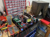
Here is the first power on test, the amp reached 3A bias current, the voltage at the LU1014D source pin was around 1.5v, and the voltage at the LU1014D drain pin was around 4.2v - pretty much spot on from the simulations.
LuFo (one leg of SuSyLu) predicted harmonic profile and THD for 8Vpp:
Measured harmonic profile and THD of LuFo for 8Vpp:
It’s good to try to understand the amp operation, but I think you have to now just trust that I verified it twice (P2P amp and LuFo PCB proper) and Vunce verified it also (that’s 3 times verified), and you should build it and see for yourself. Make a LuFo first and satisfy your curiosity as to the DC operating setpoints. Then transition the LuFo to a SuSyLu. Nothing lost as it’s all useable as a new monoblock. You just need a balanced inductor for the latter. Use a basic inductor for the LuFo (Hammond, Lundhal, MOT, etc)
Attachments
Last edited:
Please don't get me wrong, I am not questioning your design. I am just trying to understand how the LU behaves in the circuit, and if I can use any LU, or if I should look for LUs with a particularly low or high Vgs.
I am not quite sure what you mean by this. The LU was running at the different points along the curves of the diagram. The curve tracer set the prescribed Vds and Vgs voltages and then read the Ids current at each Vds / Vgs pair.
I think the above assumes you run the LU without anything above throttling the current.
I am not quite sure what you mean by this. The LU was running at the different points along the curves of the diagram. The curve tracer set the prescribed Vds and Vgs voltages and then read the Ids current at each Vds / Vgs pair.
If anyhow is interested in building the SuSyLu but doesn’t want to order their own PCBs, there is a GB signup here. You will need two pairs for a stereo amp as it is BTL and a pair per monoblock.
LuFo Amp GB
LuFo Amp GB
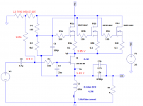
Following up on my question regarding the dissipation and bias point of the LU1014, I built a "mockup" of the LuFo circuit using parts I had on hand. The main modifications were as follows:
The LD1014 part used in the mockup has a Vgs of -0.92 V @ 2.4 V / 1.5 A, which is a bit more negative than the one used in my previous post, and the ones used by Xrk.
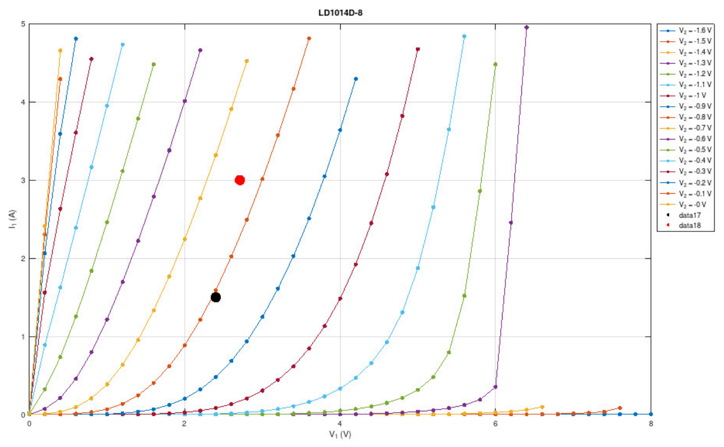
Once the cascode voltage was adjusted such that the LuFo was running at 3.0 A, I read the voltage values in the circuit as shown in the attachment. As I expected (see my earlier post), the drain voltage of the LU1014 was quite a bit higher (7.0 V) than predicted by the SPICE simulation (4.2 V). With the voltages observed in my mockup, the LU1014 dissipates (7.0 V - 1.43 V) x 3.0 A = 16.7 W, which is a bit (too) hot. Also, the bias point (red dot in the attached diagram) is not in the "nicely linear" area of the LU1014 curves.
I see two ways to cure these issues:
Both measures would reduce the drain-source voltage of the LU1014. This would result in lower dissipation and move the bias point to a "nicer" area of the curves.
- 1 x IRFP150 instead of 3 x IRFP240
- 0.47 Ohm resistor instead of choke with 0.5 Ohm DCR (I only cared about the DC operation points, so I didn't need the inductance)
The LD1014 part used in the mockup has a Vgs of -0.92 V @ 2.4 V / 1.5 A, which is a bit more negative than the one used in my previous post, and the ones used by Xrk.
Once the cascode voltage was adjusted such that the LuFo was running at 3.0 A, I read the voltage values in the circuit as shown in the attachment. As I expected (see my earlier post), the drain voltage of the LU1014 was quite a bit higher (7.0 V) than predicted by the SPICE simulation (4.2 V). With the voltages observed in my mockup, the LU1014 dissipates (7.0 V - 1.43 V) x 3.0 A = 16.7 W, which is a bit (too) hot. Also, the bias point (red dot in the attached diagram) is not in the "nicely linear" area of the LU1014 curves.
I see two ways to cure these issues:
With a fixed 1.5 VDC drop across the choke (0.5 V DCR @ 3 A), an LU1014 with an unusually high |Vgs| spec should be used to make sure it runs at a lower drain voltage.- Use a choke with a lower DCR in order to lower the DC voltage drop, and hence also the gate voltage of the LU1014.
Both measures would reduce the drain-source voltage of the LU1014. This would result in lower dissipation and move the bias point to a "nicer" area of the curves.
Attachments
Nice work. I would not worry about 16w dissipation. Where is the preferred “linear region”? I thought that’s where the curves are straight lines and not where the curved knees are. As you don’t like the earlier operating point either?
Last edited:
Mbrennwa, I would adjust the resistor string that sets the cascode voltage. I would shoot for Vds of the LU1014 to be 2.4v just as Mr Pass uses in his F3 and his Zen V9.
When curve tracing the LU, the device is unstable at Vds above around 4V. By unstable, I mean that the gain becomes crazy large and the slope of the Vgs-Id curve becomes almost infinite.
At Vds around zero, the device is saturated and behaves with a pentode-ish character.
So, you want to operate the device above the pentode-ish behavior and less than the runaway gain behavior. .
Mostly, I would operate the LU in exactly the region Mr. Pass uses in his designs. He is the master. We are the imitators.
That said, you do what makes you happy.
Last edited:
Nice work. I would not worry about 16w dissipation. Where is the preferred “linear region”? I thought that’s where the curves are straight lines and not where the curved knees are. As you don’t like the earlier operating point either?
The linear region is where the load line crosses the curves at equal distances. This usually means the bias point should be where (i) the curves are spaced equally and (ii) away from the knees.
I would shoot for Vds of the LU1014 to be 2.4v just as Mr Pass uses in his F3 and his Zen V9.
Yes. That's where I put the red dot in my diagram in post 221.
I believe the F3 and Zen V9 use a somewhat lower idle current than the LuFo, so extrapolating the curves from the F3/V9 point to the 3 A bias of the LuFo, a Vds value of about 3 V might be okay, too.
Mbrennwa, I would adjust the resistor string that sets the cascode voltage.
I believe by "cascode voltage" you are referring to "Vcascg", i.e., the voltage into the gate resistor of the cascode FET (IRFP150 in my mockup), right?
In the LuFo, the Vcascg voltage is adjusted to set the operating point of the LU1014 such that the idle current is 3 A. The Vgs of the LU1014 is set by the voltage drop across the DCR of the choke (nominally 0.5 Ohm, or 0.47 Ohm in my mockup). This means the |Vgs| value for the LU1014 is fixed at 0.5 Ohm x 3 A = 1.5 V. With Id and Vgs fixed, the Vds of the LU1014 is also fixed according to the characteristics of the LU1014. Vds will typically come out at about 5 to 8 V (depending on the Vgs spec of the specific part).
When curve tracing the LU, the device is unstable at Vds above around 4V. By unstable, I mean that the gain becomes crazy large and the slope of the Vgs-Id curve becomes almost infinite.
Would it be possible to run the the SuSyLu at a lower idle current? This would reduce the voltage drop across the choke, and hence the |Vgs| and Vds of the LU1014 would be lower, too. If my math is right, the 100 W spec of the SySyLu into an 8 Ohm load would require a 5 A peak current. I am not quite sure how the two halves of the SuSyLu contribute to the total current, and how the choke is helping, so I don't know how to work out the min. DC bias current.
Alright, here's a revised version of the circuit that allows adjusting the Vgs for the LU1014. With this fix, I was able to set the DC bias to Vds = 2.4 V. This should work with just about any LU1014/LD1014 part out there, which removes the need for special/rare 1014 parts with unusually high Vgs specs. It's therefore much easier to build this amp.
I also found that with the earlier bias (Vds = 5...8V or so), the LU1014 gate was drawing a bit of current, whereas the gate current was essentially zero at Vds = 2.4 V. I prefer the setup with zero gate current.
I'd think it should be relatively easy to modify the LuFo PCB to add this (or a similar) Vgs adjustment for the LU1014, if desired.
Attachments
That makes sense, and it also allows more flexibility in the choice of inductors witn less worry about DCR.

Thanks for trying that out Mbrennwa. Looks like a good solution, I’ll see if JPS64 can accommodate this update.
Alright, here's a revised version of the circuit that allows adjusting the Vgs for the LU1014. With this fix, I was able to set the DC bias to Vds = 2.4 V. This should work with just about any LU1014/LD1014 part out there, which removes the need for special/rare 1014 parts with unusually high Vgs specs. It's therefore much easier to build this amp.
I also found that with the earlier bias (Vds = 5...8V or so), the LU1014 gate was drawing a bit of current, whereas the gate current was essentially zero at Vds = 2.4 V. I prefer the setup with zero gate current.
I'd think it should be relatively easy to modify the LuFo PCB to add this (or a similar) Vgs adjustment for the LU1014, if desired.
Outstanding. Being able to adjust Vds make excellent sense. Each pair of LU may be slightly different for optimal Vds. Its DIY so tweaking is to be expected.
Interesting development @mbrennwa - I'm not skilled/knowledgable enough to be able to contribute but I'm watching with interest.
Eliminating the output cap is a good objective, though I would want to then include some speaker protection modules.
Have you had any further thoughts a suitable inductor?
Eliminating the output cap is a good objective, though I would want to then include some speaker protection modules.
Have you had any further thoughts a suitable inductor?
Hi Folks,
JPS64 will get to this as soon as he has some time. It’s a good option to have this adjustment though, definitely.
JPS64 will get to this as soon as he has some time. It’s a good option to have this adjustment though, definitely.
What you are actually doing is changing auto-bias into a mix of auto-bias and (as called in tube electronics) fixed bias.
To lower the bias (and current) you could also add a resistor in series with the choke, maintaining auto-bias.
To lower the bias (and current) you could also add a resistor in series with the choke, maintaining auto-bias.
Last edited:
To lower the bias (and current) you could also add a resistor in series with the choke, maintaining auto-bias.
We don't want to change the current. It should stay at 3 A, I guess.
Adding a resistor in series with the choke would INCREASE the voltage drop, and hence result in even higher |Vgs| and Vds. The whole idea was to go the other way.
Auto bias is nice if parts always have pretty much the same characteristics. That's not the case with the LU1014.
I guess you should try my ideas in a test build first. Maybe there is still a bit room for improvement (parts values etc.) with new bias circuit, as my mockup was just very quick and dirty.Hi Folks,
JPS64 will get to this as soon as he has some time. It’s a good option to have this adjustment though, definitely.
The description of the changes given in the LuFo thread seems on the mark. I like the addition of a 10 uF cap to the wiper of the new bias adjustment pot. I prefer a low ESR aluminum polymer cap for this application.
Have you had any further thoughts a suitable inductor?
For my LuFo I ordered this heavyweight thingie:
Blocked
But please wait for a confirmation from xrk especially for this amp.
I already have a pair of the Hammond 195T5 chokes, as well as the Microwave oven transformers. The Hammonds should be a good match for this amp, especially with the wider range of adjustment for the bias voltage.
- Home
- Amplifiers
- Pass Labs
- SuSyLu Where Are You?