The ones I have are wound at one time with two strands side by side to ensure nearly identical lay-down of the wires so that the inductance and DCR are identical. If a wire was wound one at a time, the bobbin would get filled with the first wire and the second one would be on top and not identical in length or exposure to the magnetic flux as that is radius dependent. Then measurements with a LCR meter and adjustments of length by hand would be needed.
I just used what came out of the parts box. I used a fixed 1 kOhm resistor from 28 V into a 50 Ohm trimmer pot to GND. For a proper build I'd user larger values.
Ok, that’s a bit too small of a resistance. Good to see the ratio though.
1050ohms across 30v is 850mW thermal dissipation. Warm to Hot!
I would go 20k resistor and 1k pot then for similar ratio and only 43mW dissipation.
The ones I have are wound at one time with two strands side by side to ensure nearly identical lay-down of the wires so that the inductance and DCR are identical. If a wire was wound one at a time, the bobbin would get filled with the first wire and the second one would be on top and not identical in length or exposure to the magnetic flux as that is radius dependent. Then measurements with a LCR meter and adjustments of length by hand would be needed.
Ok, that's the way it should be.
I just remember somewhere you mentioned suggestion to unwind secondary of MOT and put another primary in.
That would not be identical.
@Adason,
That was when I was thinking of DIY’ing my own balanced from an old MOT. After finding out that a custom balanced bifilar choke was in the cards, I gave that up. 🙂
@Mbrennwa,
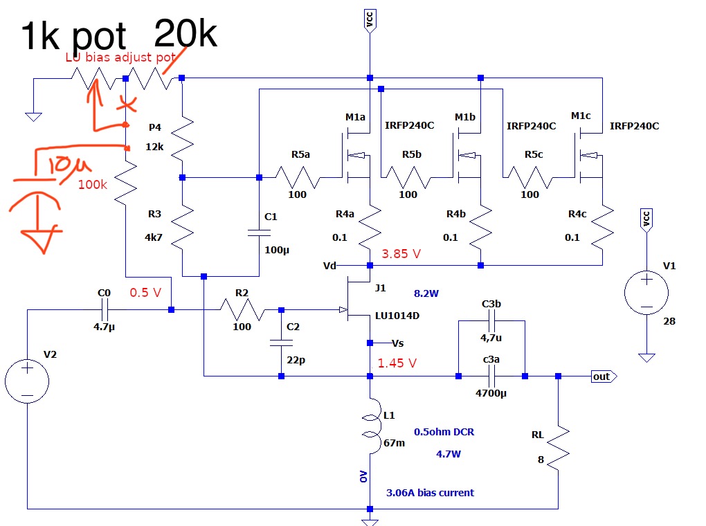
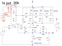
Here are the changes we will make to the layout per your suggestion of adding bias voltage adjustment for the gate of the JFET. For those who don’t want to use this option, simply jumper the 10uF cap to ground and leave off the pot and 20k resistor.
That was when I was thinking of DIY’ing my own balanced from an old MOT. After finding out that a custom balanced bifilar choke was in the cards, I gave that up. 🙂
@Mbrennwa,
Here are the changes we will make to the layout per your suggestion of adding bias voltage adjustment for the gate of the JFET. For those who don’t want to use this option, simply jumper the 10uF cap to ground and leave off the pot and 20k resistor.
Attachments
By "pot" do you mean a 20-turn trimmer? That's what I used, and I thought the multi-turn thing was good to have.
Yes, pot is short for potentioneter, typically 10 or 20 turn Bourns type blue plastic one with brass slotted screw driver knob.
Alright, here's a revised version of the circuit that allows adjusting the Vgs for the LU1014. With this fix, I was able to set the DC bias to Vds = 2.4 V. This should work with just about any LU1014/LD1014 part out there, which removes the need for special/rare 1014 parts with unusually high Vgs specs. It's therefore much easier to build this amp.
I also found that with the earlier bias (Vds = 5...8V or so), the LU1014 gate was drawing a bit of current, whereas the gate current was essentially zero at Vds = 2.4 V. I prefer the setup with zero gate current.
I'd think it should be relatively easy to modify the LuFo PCB to add this (or a similar) Vgs adjustment for the LU1014, if desired.
Hi Mbrennwa,
I addedthe JFET gate bias mod you suggested to the simulation and noticed that the overall output stage bias current rises with an increase the gate bias voltage (as expected since N-ch JFET needs a negative voltage to pinch-off). Did you have to iteratively adjust the cascode bias voltage pot with the JFET gate bias voltage pot to achieve the desired overall bias current and JFET Vds of 2.4v? I was not able to find a setting in LTspice that gave me Vds of 2.4v AND a 3.06A bias current overall, except whent I set the pot for the JFET gate to 0 ohms (back to original circuit).
Maybe it is not working because the model of the JFET I have in LTSpice is for a higher Vds unit?
Yes, its an iterative process. Adjusting the LU gate bias will affect the idle current and cascode operating point -- and vice versa.
It's not surprising that your SPICE model for the LU wants the LU gate at ground, as this is how it was before the bias mod. That SPICE LU model is obviously just a model, not reality. You could do a curve trace in SPICE and compare it with the measured curves to see the differences.
It's not surprising that your SPICE model for the LU wants the LU gate at ground, as this is how it was before the bias mod. That SPICE LU model is obviously just a model, not reality. You could do a curve trace in SPICE and compare it with the measured curves to see the differences.
I have been staring at the transformer / balanced choke for quite a while, and now I suddenly realized that there's something that confuses me: what about the polarities of the winding relative to each other? I see two ways:
- The windings are wired such that their magnetic fluxes cancel each other, leaving the total magnetic flux at approximately zero when there is not audio signal.
- The windings are wired such that their magnetic fluxes add up.
Check how a push pull tube output transformer is wired, because DC / AC wise it is exactly the same.
Try to understand the difference between DC and AC.
Try to understand the difference between DC and AC.
In the LTSpice model, note the orientation of the dots on the balanced inductor windings. If you flip it, it doesn’t work. And in reality I tried it - the amp produces highly distorted output.
Here is how I see it: The DC field cancels (opposite polarities). The AC field is reactive and in opposing phase so doubles the back EMF and hence where we get the pull from the push to increase the swing beyond the rail voltage.
Here is how I see it: The DC field cancels (opposite polarities). The AC field is reactive and in opposing phase so doubles the back EMF and hence where we get the pull from the push to increase the swing beyond the rail voltage.
Check how a push pull tube output transformer is wired, because DC / AC wise it is exactly the same.
Try to understand the difference between DC and AC.
I guess you are referring to the primary of a (triode) push pull, right? I am actually not sure how this is done. Again, I see two ways (and they are basically equivalent to the two options in my previous question):
- The winding is done by winding a single wire onto the core, and tapping it off in the middle to make the center tap. The currents from the center tap to the ends of the winding therefore flow in opposite directions.
- The winding is done by simultaneously winding two wires onto the core. The two wires are joining to form the center tap (either at the beginning of the windings or at the end of the windings). The currents from the center tap to the ends of the winding therefore flow in the same directions.
In the LTSpice model, note the orientation of the dots on the balanced inductor windings.
Ha, I didn't see the dots, and then I had to look up the meaning of the dots... thanks for pointing this out. 🙄
Let's see if I get this right: when winding the transformer, both wires are wound onto the core in parallel ("bifilar winding"). Both wires are marked with a "dot" at the beginning of the windings, and with "no dot" at the ends. Then the windings are connected with the dots as in the schematic of the first post. Correct?
On a Bifilar wound with two simultaneous wires. Connect start of one wire the end of the winding of the other. Since the two are independent you can wire it anyway you want.
A choke with center tap may or may not be wound correctly to allow this.
To answer your question above: yes. Dot on one winding to source of JFET if one leg and no dot to other leg source JFET.
A choke with center tap may or may not be wound correctly to allow this.
To answer your question above: yes. Dot on one winding to source of JFET if one leg and no dot to other leg source JFET.
I found a transormer maker who is willing to make these for me. He asked if the 0.1 mm airgap is the true geometric width of the gap, or of this is the effective width in the sense that the gap is distributed across the three "joints" where the E and I meet. In other words, the magnetic flux passes the gap once at the middle of the E, and then a second time at the top/bottom of the E. Since the flux passes the gap twice, the effective width is twice as much as the real geometric width. Soooo, which one does the "0.1mm airgap" refer to?The specs are 600VA class EI core made of grain oriented silicon steel (GOSS). There is a 0.1mm airgap.
Ok, thanks. It looks like the manufacturer did not wait for my feedback on the gap size, as the postman delivered the chokes/transformers this morning. I briefly checked the inductivity vs frequency, and it looks good (way higher than 60 mH all the way up to 25 kHz, DC resistance is 0.4 Ohm). However, this quick test was with no DC load on the windings. What would be a good test setup to test the chokes with a DC load?
The easiest way is to run it in the amp and see what setpoints you get. To build a rig to run 3A with appropriate voltages is not trivial. Might as well use real thing. I think you will be fine. Can you show photos?Ok, thanks. It looks like the manufacturer did not wait for my feedback on the gap size, as the postman delivered the chokes/transformers this morning. I briefly checked the inductivity vs frequency, and it looks good (way higher than 60 mH all the way up to 25 kHz, DC resistance is 0.4 Ohm). However, this quick test was with no DC load on the windings. What would be a good test setup to test the chokes with a DC load?
That was fast!
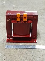
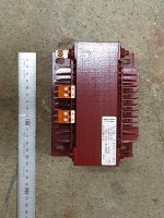
The chokes were made by Wagner + Grimm in Switzerland. They are big, heavy, and red 🙂
Photos and measured impedance and inductance data are attached. DC resistance is 0.4 Ohm per winding.
If testing them in an amp, what would you look out for? How can I tell if they are running into saturation?
Photos and measured impedance and inductance data are attached. DC resistance is 0.4 Ohm per winding.
If testing them in an amp, what would you look out for? How can I tell if they are running into saturation?
Attachments

- Home
- Amplifiers
- Pass Labs
- SuSyLu Where Are You?