Hyperbolic horns with T < 1 will approximate the exponential horn expansion a certain distance from the throat
A hyperbolic horn with T = 1 has an exact exponential expansion over the full length of the horn.
Attachments
The cutoff frequency of an infinite conical horn is given by k * xt = 1, where:
k = wave number = 2 * Pi * f / c
xt = distance from the apex to the throat
c = speed of sound
Therefore:
fc = c / (2 * Pi * xt)
In the attached example:
c = 34400 cm / sec
xt = 10 cm
fc = 34400 / (2 * Pi * 10) = 547.49 Hz
Hi David, if i did the math right for the example you gave using 10cm apex to throat (xt), i get that would equate to a 20 degree pattern horn.
Using a 90 degree horn and a 1.4" throat, i get an xt of 1.778 cm (1/2 the throat diameter). Which would take cutoff of an infinite conical to 3079Hz.
Hope the math is correct...just checking to see first..
....before postulating that given the math is both for infinite horns, and that horns generally have fairly wide patterns which will shorten the xt distance......well it seems from a pragmatic point that conical cutoff is pretty much immaterial.
Am i missing something?
thx!
The cutoff frequency of an infinite conical horn is given by k * xt = 1, where:
k = wave number = 2 * Pi * f / c
xt = distance from the apex to the throat
c = speed of sound
Therefore:
fc = c / (2 * Pi * xt)
In the attached example:
c = 34400 cm / sec
xt = 10 cm
fc = 34400 / (2 * Pi * 10) = 547.49 Hz
David, in the sim you demo'd here, can you share the input or file please.
Camplo.
8000+ posts.
Lots of help from experts.
And you still didn't even start to build something?
LOL.
8000+ posts.
Lots of help from experts.
And you still didn't even start to build something?
LOL.
I am trying to reverse engineer the ideas from the electrical impedance....If you own the horn there is no need to reverse engineer, just read the measurements lol. Marks approach nulls the parts that he cared about...Group Delay....
I trust Marks ears....I don't trust the "cutoff" that manufacturers tell their customers lol....My guess is that this horn is the biggest horn in his arsenal at least applied to his experience of going "low" with compression drivers....and his "Big" horn is only faithfully loading, in my description of desired performance, down to 400hz lol, to which I would want a crossover closer to 600hz-800hz according to theory I've applied here. Mark said he didn't like it crossed low....think about it. Mark correct me where I have assumed incorrectly about your experience with big horns and compression drivers crossed low...but in regards to the Me646 Horn. I am assuming that the trend is holding true, to allow me to reverse engineer these thoughts, by means of electrical impedance and this horn is best crossed much higher than 300hz... Or better said... This horn is not suitable for playback down to 300hz.
Camplo, i need to comment on several observations you have made about my posts.
Back somewhere you made one about my "philosophy" for sizing an amp to a speaker's wattage rating.
No philosophy to it.
It's about some simple math that equates amp rail voltages needed to drive instantaneous signal peaks, and a general knowledge of what amplifier power ratings really mean in terms of their rail voltages (max voltage available)
With regard to my listening experiences with the me464....I've had very little listening time with it. It is unfair for me to offer any definitive conclusion on how low it might work with any CD.
I tried the dcx464 with it on top of a single sealed 18" to quickly see if it might live up to this thread's quest...a 2-way. I'm so into synergies right now, what i heard didn't compel me to continue on with it. That's all i can really say.......
With regard to the small mids improving sound on current syns....they do.
I don't know why.
It may be because the CD's don't sound as good taken lower, or it may be the driver interactions in a synergy have more going on than realized, or for that matter, it may be the small mids are also taking some of the higher frequency response away from larger cones that were previously covering that range....i dunno. Which is it, any or all?
And I have a request...please stop using your own terminology such as tuning note, the root mode etc. It's very annoying when folks want coin their own phrases for what already has good well known scientific terminology.
We have a hard enough time communicating and understanding the common terminology.
Seems arrogant to bring new terms to the party unless they truly describe something new. Which so far i haven't heard.
All i've heard is that group delay and excursion go up in the low corner.....and look at all the graphs that show/prove it.
Well duh, they do go up in the low corner...who doesn't know that?
Grec it is an unfair comment: Camplo built is already well started ( take a look into the subwoofer subforum) and issues with drivers probably delayed the build even further. Not to forget Camplo seems to have bought every possible horn he could in order to test them!
But yes, i think too it's time to stop running in circles chasing his tail about 'details'.
I mean theory is great ( i love theory) but practice you can't skip to improve things, which can't be perfect first try ( or by luck)...
But yes, i think too it's time to stop running in circles chasing his tail about 'details'.
I mean theory is great ( i love theory) but practice you can't skip to improve things, which can't be perfect first try ( or by luck)...
All horns have resonance.....
I am sorry, but this is not true. All drivers have resonances, but a good waveguide will not.
Also, you keep referring to you "theory" but I am not clear on what it is. Could you describe what it is?
I am sorry, but this is not true. All drivers have resonances, but a good waveguide will not.
Also, you keep referring to you "theory" but I am not clear on what it is. Could you describe what it is?
Are we talking on a practical level or academic level?
Coming up with a shape that is so extremely irregular is just extremely difficult.
Eventually there will always be some kind of resonance of some kind.
That can be even a tangential or oblique one.
Sometimes very small, out of frequency band and (maybe) not noticeable.
But that doesn't mean it's not there.
Yes, I am aware that is (very) nit picky, but without giving any order of magnitude or reference I don't know what level we are talking about.
Some people and even whole companies seem to really care about those microscopic baffle resonances that also don't have any practical value anymore.
So I thought it is at least worth putting it a tiny bit into perspective at least.
The statement on an absolute level isn't true.
On a practical level, yes I fully agree.
The thing about horns and waveguides is that they can be complex and sometimes I bet things don't line up how I think they should but generally speaking
We should find the same trend on this horn. When applying the approach, crossing 2x (or more apparently) above cut off...This, is the area that I would consider to base that point from....Group Delay is likely is peaking here, as well as Decay....
Here being the Highlighted area on the picture above....
This horn, based on these ideas, is only good from 800hz apparently.......Emphasis on "based on these ideas" because I said above, Horns and the different expansion rates, and design approaches can cause complex results that may veer from how I've seen things go with tractrix and jmlc....So an analysis of measurements would be the right thing to do before throwing the book at this horn. I am trying to reverse engineer the ideas from the electrical impedance...
The electrical impedance alone won’t allow you to derive the acoustic impedance at the throat, unless you have a very accurate two-port model of the compression driver used to drive it. To get that, you'll need an anechoic termination in a rather long plane wave tube, plus a rigid termination with space for high quality microphones.
See Makarski's papers:
AES Journal Forum >> Two-Port Representation of the Connection between Horn Driver and Horn
There's also a promising method that derives the two-port model using only electrical measurements and a known acoustical load impedance, but I havent been able to try this one:
AES Convention Papers Forum >> Determining Two-Port Parameters of Horn Drivers using only Electrical Measurements
This might me useful for creating lumped element models for use in Ath4 @mabat
You can also DIY a simple plane wave tube, and use the single 'moving mic' technique with lots of averages to measure the throat impedance.
I am aware that is (very) nit picky.
So am I.
It takes a reflection from the mouth of the device to create any kind of internal resonance. Now, there is always "some " level of mouth reflection, yes, but then one can always design for less.
Camplo.
8000+ posts.
Lots of help from experts.
And you still didn't even start to build something?
LOL.
Should I respond to this or just let it linger in front of those who know what you do not. A much more sophisticated laugh out loud =P
Camplo
And I have a request...please stop using your own terminology such as tuning note, the root mode etc. It's very annoying when folks want coin their own phrases for what already has good well known scientific terminology.
We have a hard enough time communicating and understanding the common terminology.
Seems arrogant to bring new terms to the party unless they truly describe something new
Im scared to call it cut off, let me investigate that term a little more
Tuning note is not an inaccurate term or unfamilar terminology for vented designs I thought...,
4 : to adjust the frequency of the output of (a device) to a chosen frequency or range of frequencies
: to adjust the frequency of the output of (a device) to a chosen frequency or range of frequencies
Martin King says tuning so the term isn't new out of all things.
http://www.quarter-wave.com/Horns/Horn_Physics.pdfDesign of an Exponential Horn Tuned to 100 Hz :
Assuming that the desired lower cut-off frequency fc of an exponential horn is 100 Hz,
I'm not trying to be arrogant and create my own lingo… If you use the dictionary those terms to fit the description....I'm scared to call it cut off until I know for sure that the cut off always is in this area that I am looking at and calling the "tuning" "tuning note" "root mode" etc now that I think of it, I am trying to point to the area of Max horn resonance aka max loading… If I am correct cut off is not exactly at this place...slightly below it, I think.
Last edited:
Transmission, Transformation, Attenuation, Propagation
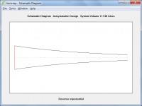
Martin King is using exponential horn geometries to attenuate the bass backwave with minimum reflection back to the driver at the mouth. The bass driver is at the mouth of the horn. The throat is the open backwave exit.
It’s the reverse of a high pass horn, where the driver is at the throat of the horn, and propagation is at the mouth; hopefully with minimum reflection back to the throat.
If the bass transmission line reverse exponential horn system is built properly, you have predominately resistive attenuation of the backwave to low frequencies determined by So, SL, and L(the length of the tube/horn). Notice how L(length), and So(area of the throat), can remain constant, while varying SL(area of mouth), and Fc changes by a factor of 4.5. Varying SL is like varying the flare rate. See Table 5.2 in the Martin King pdf.
Don’t confuse bass transmission line ‘tuning’ with high pass horns just because they can both use an exponential taper, and can both be called transmission lines. The goals are opposite.
Think the bass section of something like this:
Uniwersum MK 4 – hORNS
Think of a foam plug filling that big tapered bass tube.
Or, try speaking into the mouth of a horn and listen to what comes out of the throat. Do it after filling the horn with stuffing.
For a little reference – from “High Quality Horn Loudspeaker Systems”
11.6 Transmission lines, page 441
“… Smooth tapering according to a prescribed law, for instance exponential or hyperbolic can give low-reflection wide-band impedance transformation.
The horn can be regarded as a tapered acoustic transmission line, and if properly designed and terminated, can give nearly reflection-free transformation over a wide frequency band”.
Both the bass transmission line and the high frequency CD/Horn can give ‘nearly reflection-free transformation’. The bass transmission line gives backwave attenuation. The CD/Horn ‘transmission line’ gives amplified frontwave propagation. One of these things is NOT like the other, even though they both use horns.
Last edited:
Hi Mark,
Strange as it may seem, because fc varies with xt only, it is possible to specify multiple infinite conical horns with different sizes and flare rates all having the same cutoff frequency.
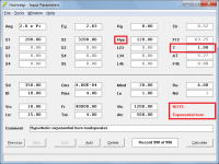
In my example I assumed a throat radius of 5 cm, a mouth radius of 40 cm and a horn length of 70 cm. The Hornresp inputs required to specify the infinite conical horn were:
Ang = 0.0 x Pi
S1 = 78.54 cm^2
S2 = 5026.55 cm^2
L12 (Con) = 70.00 cm
This gives:
xt (rounded to two decimal places) = 10.00 cm
Fta (flare tangent angle) = 26.57 degrees
fc = 547.49 Hz
If I had instead assumed a throat radius of 8 cm, a mouth radius of 64 cm and a horn length of 70 cm, the Hornresp inputs required to specify the infinite conical horn would have become:
Ang = 0.0 x Pi
S1 = 201.06 cm^2
S2 = 12867.96 cm^2
L12 (Con) = 70.00 cm
This gives:
xt (rounded to two decimal places) = 10.00 cm
Fta (flare tangent angle) = 38.66 degrees
fc = 547.49 Hz
So even though in the second example the throat size is larger and flare rate higher, because xt = 10 cm in both cases, the fc values are identical. If the normalised acoustical throat impedances for the two horns are compared, it can be seen that the two traces (and therefore the fc values) are the same.
Agreed. I find it all quite interesting from a theoretical / academic point of view though 🙂.
Kind regards,
David
if i did the math right for the example you gave using 10cm apex to throat (xt), i get that would equate to a 20 degree pattern horn.
Strange as it may seem, because fc varies with xt only, it is possible to specify multiple infinite conical horns with different sizes and flare rates all having the same cutoff frequency.
In my example I assumed a throat radius of 5 cm, a mouth radius of 40 cm and a horn length of 70 cm. The Hornresp inputs required to specify the infinite conical horn were:
Ang = 0.0 x Pi
S1 = 78.54 cm^2
S2 = 5026.55 cm^2
L12 (Con) = 70.00 cm
This gives:
xt (rounded to two decimal places) = 10.00 cm
Fta (flare tangent angle) = 26.57 degrees
fc = 547.49 Hz
If I had instead assumed a throat radius of 8 cm, a mouth radius of 64 cm and a horn length of 70 cm, the Hornresp inputs required to specify the infinite conical horn would have become:
Ang = 0.0 x Pi
S1 = 201.06 cm^2
S2 = 12867.96 cm^2
L12 (Con) = 70.00 cm
This gives:
xt (rounded to two decimal places) = 10.00 cm
Fta (flare tangent angle) = 38.66 degrees
fc = 547.49 Hz
So even though in the second example the throat size is larger and flare rate higher, because xt = 10 cm in both cases, the fc values are identical. If the normalised acoustical throat impedances for the two horns are compared, it can be seen that the two traces (and therefore the fc values) are the same.
it seems from a pragmatic point that conical cutoff is pretty much immaterial.
Agreed. I find it all quite interesting from a theoretical / academic point of view though 🙂.
Kind regards,
David
Last edited:
can you share the input or file please.
Hi camplo,
See my post above for the details.
Kind regards,
David
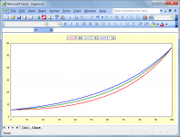
Hyperbolic horns with T < 1 will approximate the exponential horn expansion a certain distance from the throat
The attachment compares the flare profiles for T = 0 (catenoidal), T = 0.5 (cosh) and T = 1 (exponential) hypex horns having the same throat areas, mouth areas and axial lengths.
Attachments
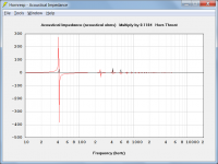
Martin King is using exponential horn geometries to attenuate the bass backwave with minimum reflection back to the driver at the mouth. The bass driver is at the mouth of the horn. The throat is the open backwave exit.
Attachment 2 shows the acoustical impedance loading the rear side of the driver diaphragm for the undamped (no absorbent filling material) system given in Attachment 1.
Attachments
Hi Mark,
Strange as it may seem, because fc varies with xt only, it is possible to specify multiple infinite conical horns with different sizes and flare rates all having the same cutoff frequency.
Thank you David,
I wish all the professors I've encountered through life were as clear, patient, and kind as you!
Yes, nothing says that only a compression driver can go on the throat of a horn, huh? 🙂
Paul
Open and closed pipe physics...configure the pipe this way, its called this....stuff it with damping material it now does that....
Its all bound to the same rules.....
Open and closed pipe physics...configure the pipe this way, its called this....stuff it with damping material it now does that....
Its all bound to the same rules.....
- Home
- Loudspeakers
- Multi-Way
- Is it possible to cover the whole spectrum, high SPL, low distortion with a 2-way?