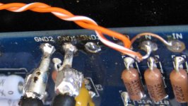
The RCA connect the center to +IN and the ring to GND at the PCB.
Take a short wire and connect -IN to GND on the PCB.
EDIT: as boky shows below.
Take a short wire and connect -IN to GND on the PCB.
EDIT: as boky shows below.
Last edited:
Well, that earned me an offset correction and a ever so slight hum. I think the image is more solid, but I'm not so certain I prefer the difference. Perhaps I'll try balanced input. If I'm not mistaken that configuration would be as I had it with one of the balanced input connector pins grounded to the chassis.
Last edited:
The single, most important improvement that balanced topology and proper grounding and return of common currents brings (with a single PS PCB), is in... phase position and placement of instruments in the 3-dimensional soundscape. It is routinely, completely overlooked. This is (one of the reasons) why a dual power supply sounds so good with AlephJ
Has anyone built and compared two? I don't doubt it sounds better, but if I were to say upgrade my configuration to a dual PS, I would obviously declare it sounds better after the fact.
I have the antek 300V 20V transformer. I see you can stack them with taller hardware? I assume you would just parallel the primary and secondary connections of each transformer. Where I get lost is the configuration of PS boards. Do you double up on the rectification?
Oh dear... a rabbit hole...
I have the antek 300V 20V transformer. I see you can stack them with taller hardware? I assume you would just parallel the primary and secondary connections of each transformer. Where I get lost is the configuration of PS boards. Do you double up on the rectification?
Oh dear... a rabbit hole...
Dual mono would mean two completely separate power supplies, one for each channel. So you would need another pair of bridges, another PS board, etc.
.....
Oh dear... a rabbit hole...
Peppe pointed you to properly shown innards of Rabbit Hole in post #7157
Has anyone built and compared two? I don't doubt it sounds better, but if I were to say upgrade my configuration to a dual PS, I would obviously declare it sounds better after the fact.
I have the antek 300V 20V transformer. I see you can stack them with taller hardware? I assume you would just parallel the primary and secondary connections of each transformer. Where I get lost is the configuration of PS boards. Do you double up on the rectification?
Oh dear... a rabbit hole...
Did you post a pic of you PSU? Problem solved or still hum?
You can mount the transformers like this.Has anyone built and compared two? I don't doubt it sounds better, but if I were to say upgrade my configuration to a dual PS, I would obviously declare it sounds better after the fact.
I have the antek 300V 20V transformer. I see you can stack them with taller hardware? I assume you would just parallel the primary and secondary connections of each transformer. Where I get lost is the configuration of PS boards. Do you double up on the rectification?
Oh dear... a rabbit hole...
Attachments
Did you post a pic of you PSU? Problem solved or still hum?
Its not enough of a hum to bother. Since grounding IN-, I no longer need to ground my source chassis, it makes no difference.
You can mount the transformers like this.
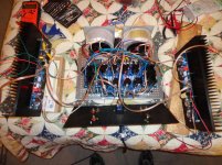
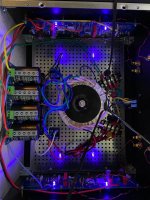
Google search results (diyaudio) indicate I could stack the power toroidals with the only concern being heat. I think there is room on the front plate for two PSU boards - that way I could keep my existing layout with minimal changes.
Attached is the my current layout. Mind the wire running across the top, that is just a hack for a couple 140mm case fans I have strapped to the sides. All heat issues are resolved, -15C to -20C drop everywhere.
Attachments
Talkin' out donuts... Have anybody tried this totoid from RS? Obviously two in dual mono:
Trasformatore toroidale RS PRO, 225VA, primario 115V ac, 230V ac, secondario 2 x 18V ca | RS Components
Trasformatore toroidale RS PRO, 225VA, primario 115V ac, 230V ac, secondario 2 x 18V ca | RS Components
Google search results (diyaudio) indicate I could stack the power toroidals with the only concern being heat. I think there is room on the front plate for two PSU boards - that way I could keep my existing layout with minimal changes.
So according to what I see in the Sissy layout, I could split the existing PSU board and just run one to each board? I saw CRCC used on the PS output. That's some nice looking caps on the last line of C for the PS.
Also, pouring over the schematic last night... It looks like I could just potentially remove C1 and make eg. C6 a boutique film cap. It seems a more obvious target to me. I see a lot of replacements on C1 - guessing you would amplify the characteristics of the C1 position making it more noteworthy.
Is there a rough bypass size rule? The C6 in this case seems to be .1%
Could you split one PSU board in half and then run each half of that PSU board to one channel of the amplifier? No.
You need a bipolar PSU on each amp channel.
You need a bipolar PSU on each amp channel.
So according to what I see in the Sissy layout, I could split the existing PSU board and just run one to each board? I saw CRCC used on the PS output. That's some nice looking caps on the last line of C for the PS.
Also, pouring over the schematic last night... It looks like I could just potentially remove C1 and make eg. C6 a boutique film cap. It seems a more obvious target to me. I see a lot of replacements on C1 - guessing you would amplify the characteristics of the C1 position making it more noteworthy.
Is there a rough bypass size rule? The C6 in this case seems to be .1%
The nice looking caps are Ducati 50uF decouplers, simply to create another reaonant frequency mostly iot improve highs. Papa’s supplies in some instances use 10uF. I don’t think a decoupler would put a new C in the CRC, simply because it’s function is not smoothing per se.
Maybe I am at a bit of a loss here, but may I ask what your issue with the PSU is as of now?
I have had PSU issues, and found myself doing a PSU «my own» way, making it more difficult to troubleshoot. 6L6’s in the guide is quiet unless he has stated otherwise, which he has not. ZM’s way differs, but is equally quiet, and follows the same good principle. If you can get hold of his PSU boards, you’ll get a theoretically better ground tracing than the store boards. That’s not to say the store boards aren’t quiet, but simply stating a small weakness partly made up by the fact they are made to be split up if needed and as such the gnd tracing cannot be perfect.
I notice some people put their smoothing banks at the front plate. This forces transformers to be placed more mid-chassis, bringing both them and graetz bridges/rectifiers closer to the circuit. Following the standard, examplified by 6L6 numerous times, is a wise choice as it brings the most noisy parts of the circuit away from gain stages and signal wiring, according to Papaland recipe.
A completely different way is doing P2P, which I am in the process of doing. I can say it is a bit time consuming. Having things on a PCB is a bit easier. But I swore some time ago I would make one, so there we are.
The world is full of bad ideas, many of them tried before. It is also full of people willing to try and prove the bad ideas good. Dunno what I am trying to do, but I enjoy every minute of it. So who cares.
PS: Follow 6L6’s advice always, and as a general rule don’t split the boards in a Pass power amp build - ever, for any reason. They need +/0V + 0V/- (bipolar). Nothing good can come of it, unless you know exactly what you are doing and why. If you split as suggested, you end up with two half PSU’s, and that doesn’t work. In short, you’ll be missing a wire with either pos or neg polarity. Cubicincher has had success with spltting, but he is - well - cubicincher, and of course still used both polarities. Example in BA-3 guide thread.
Though maybe if you really enjoy a good bass thump, you may attempt to connect two boards of the same polarity to your circuit. The thump would probably be a one-off though

Jokes aside, I wish you luck!
Regards,
Andy
Last edited:
Maybe I am at a bit of a loss here, but may I ask what your issue with the PSU is as of now?
No real issue I don't think. There is a 60hz hum, but you have to ear the speaker to hear it. I previously had the amp boards wired incorrectly for SE input. I was not grounding the IN-, instead ran it to the floating GRD that is on the SE input connector - and I'm not using a shielded cable. Oddly my previous configuration was perfectly silent but going the proper route has created this slight hum. *shrug* It's likely a ground connectivity issue somewhere. I've not really troubleshot it deeply yet, I have been too busy enjoying the musics!

My other questions just revolve around dual mono requirements, balanced inputs and possible positions for boutique caps. Regarding dual mono, that seems simple enough. I just have to do what I've already done from between AC and amp boards. 😉 I shall make it fit. 😀
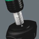
0.9
can't suggest a wrench, I was lucky - bought first one new for 1/4 of regular price, recalibrated it from 1.2 to 0.9
bought second one SH for 15E, recalibrated it from 1.5 to 1.2
now I have first for M3, second for M4
M4- handy to think less while dealing with pucks
Dear Zen Mod, if a tool can only be set to either 0.85 Nm or 0.95 Nm, what would be prefered?
I was reading datasheet of resistors in TO-247 housing, Powertron FPR2-T218 and Mundorf M-Resist Ultra.
Both datasheets specify Max. Torque - 1 Nm
Vishay IRFP240 datasheet for example specify Max. Torque - 1.1 Nm
Attachments
- Home
- Amplifiers
- Pass Labs
- Aleph J illustrated build guide