@jan.didden,
Congrats on getting your DD amp up and running!
Looking forward to whatever details you can share about the circuit once you have all the bugs ironed out.
If you take a near field measurement you should see a LF response similar to those shown in the attached images in this post: Quad esl resonance damping: how?
Congrats on getting your DD amp up and running!
Looking forward to whatever details you can share about the circuit once you have all the bugs ironed out.
No, the natural rolloff is due to the under-damped 2nd order HP mechanical response created by the diaphragm resonance. With constant drive from the amplifier(or amplifier + transformer), the diaphragm excursion will not increase below resonance. (This is similar in concept to a dynamic woofer in sealed box)… is that natural rolloff caused by the xformers and xover parts?
If you take a near field measurement you should see a LF response similar to those shown in the attached images in this post: Quad esl resonance damping: how?
Not that this has any bearing on your final results now that you are EQing based on microphone measurements, but just curious if you ever figured out why measurements were different between the setups? One thing I had meant to ask, did you try swapping the connections to the differential probe? Ideally if there is no common mode contamination to the measurement you should get the same response but with opposite phase. I recall having issues with this when I was measuring the response of A SoundLab A-1 interface for different setting of the MID and LF controls. Eventually I had to borrow a Jensen Input transformer to get rid of the problem.Yes there seems to be a difference. In this case, I applied the probe EQ after the measurement rather than to the source level, I have to see if that has introduced an error.
Full Range Electrostatic Question
… I plan to wind up some inductors this weekend that more closely match the winding geometry(ie starting from near zero radius) and see if I can get a better estimate of the coupling factors to use.
I did finally get the time to wind up some inductors more similar to the size and proportions of the actual delay-line inductors.Here is the version when cross-coupling the inductors with K=0.3 for the adjacent and K=0.1 for those one place further.
The new measurements show that the original estimate was not too far off.
New coupling factor estimates are:
K=0.25 (adjacent inductors)
K=0.05 (inductors one place further down the line)
Attachments
Last edited:
Not that this has any bearing on your final results now that you are EQing based on microphone measurements, but just curious if you ever figured out why measurements were different between the setups? One thing I had meant to ask, did you try swapping the connections to the differential probe? Ideally if there is no common mode contamination to the measurement you should get the same response but with opposite phase. I recall having issues with this when I was measuring the response of A SoundLab A-1 interface for different setting of the MID and LF controls. Eventually I had to borrow a Jensen Input transformer to get rid of the problem.
Full Range Electrostatic Question
I never followed that up unfortunately. I did notice that the amplifier I used in the test (a 200W class D) did not have a very flat response when driving the '63, so that may have been a factor.
Jan
@jan.didden,
Congrats on getting your DD amp up and running!
Looking forward to whatever details you can share about the circuit once you have all the bugs ironed out.
No, the natural rolloff is due to the under-damped 2nd order HP mechanical response created by the diaphragm resonance. With constant drive from the amplifier(or amplifier + transformer), the diaphragm excursion will not increase below resonance. (This is similar in concept to a dynamic woofer in sealed box)
If you take a near field measurement you should see a LF response similar to those shown in the attached images in this post: Quad esl resonance damping: how?
Thanks, got it.
Jan
Last edited:
I did finally get the time to wind up some inductors more similar to the size and proportions of the actual delay-line inductors.
The new measurements show that the original estimate was not too far off.
New coupling factor estimates are:
K=0.25 (adjacent inductors)
K=0.05 (inductors one place further down the line)
Hi Steve,
Great to have these values confirmed.
I've adjusted the model to these two values, but as expected, it makes very little difference.
Even making the second coupling factor K=0 does very little.
But nonetheless, your figures are exact and the model is updated.
Hans
.
Attachments
I did, but then got sidetracked with an upcoming move of my household and my lab. Sometimes life interferes with your plans ...
Jan
Jan
Yes, it's not always easy to find time for the fun stuff. I was just curious.
I'm also in the process of rebuilding house. Has taken far longer than it should... oh. well.
Mogens
I'm also in the process of rebuilding house. Has taken far longer than it should... oh. well.
Mogens
After a long silence, I'm getting close to completing the direct drive monoblocs. The whole thing must be ready for an audio show this fall.Yes, it's not always easy to find time for the fun stuff. I was just curious.
I'm also in the process of rebuilding house. Has taken far longer than it should... oh. well.
Mogens
I've also been working on a refinement: to be able to switch the speaker stators between the outputs of the step up xformers and the direcdt drive outputs.
I'm putting a small PCB with 4 SPST HV relays inside the speaker pedestal, ESL 989's. That should make for an interesting comparison. Hopefully.
Those two paths need to be carefully equalised as to freq response and level of course.
This afternoon I did some testing to validate the test method to measure levels and freq response directly at the stators.
For now, only xfrmr driven.
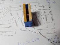
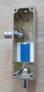
I have a pair of very high quality and very accurate 1:1000 attenuators, see pic, they come from a high voltage calibrator. I hung one on each transformer output, and the two 1:1000 atennuated outputs go to the balanced input of the AP analyzer. I measured the freq response and saw a large drop from about 10k (this is with a single ESL 63). Is that something I should have expected?
I did separately measure the amplifier and attenuation path and these are pretty flat, so it really is the speaker.
What I am not sure about is whether a 1M load on the transformer would skew the result.
Edit: it does match reasonably with what I measured last year in post 345 so I guess I'm doing it OK with the precision attenuators.
Comments invited!
Jan
Attachments
Last edited:
Do you have details on the attenuators? Series R and shunt C? Have you been able to check them? Both input Z and attenuation could affect them. If you were on this side of the pond I would lend you a pair of P6013 HV probes. Accurate nonobtrusive measurements of high voltages are simply hard to do. However you can confirm the effect of connecting them acoustically.
Also the BNC connector is only good to 500V RMS. There is a special variant https://www.amphenolrf.com/000-27000.html rated to 3500V. I first encountered it in adapters for by AC calibration stuff.
Are you using a single amp for the speaker or multiples? Given a clean sheet, I would be using one amp per "ring" and drive them with DSP so I can fully tune them.
Last edited:
The attenuators are from some Fluke 5215A calibartion amps where they are used up to 1100V @ 100kHz. Impedance is 1M/1k.
They don't have the BNC's shown in the pics, the originals have a half inch teflon clad pin sticking out, a pair is mounted in a small enclosure with an XLR as output. I have several of them, the one in the pic are for 'normal' low voltage use.
I'm using one amp per stator, two in a monobloc setup. It's important to place the amp close to the speaker, it's easy to lose half the drive current into the capacitances of the connecting cables! I have a set of cables with the HV BNCs but they have too much capacitance to be of use for this, I'm brewing my own.
But at HV, everything is expensive. The 5-pin HV LEMO connectors go for € 50 each. That's € 100 for a plug and socket ...
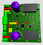
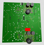
BTW Here's the PCB bottom view. It's interesting to mix analog, switching and tubes in the same area.
Jan
They don't have the BNC's shown in the pics, the originals have a half inch teflon clad pin sticking out, a pair is mounted in a small enclosure with an XLR as output. I have several of them, the one in the pic are for 'normal' low voltage use.
I'm using one amp per stator, two in a monobloc setup. It's important to place the amp close to the speaker, it's easy to lose half the drive current into the capacitances of the connecting cables! I have a set of cables with the HV BNCs but they have too much capacitance to be of use for this, I'm brewing my own.
But at HV, everything is expensive. The 5-pin HV LEMO connectors go for € 50 each. That's € 100 for a plug and socket ...
BTW Here's the PCB bottom view. It's interesting to mix analog, switching and tubes in the same area.
Jan
Attachments
Hi Jan,
Do you know the output impedance of your amps?
looks like it is very high if your cables make such an impact .
best regards,
Do you know the output impedance of your amps?
looks like it is very high if your cables make such an impact .
best regards,
The Zout is about 3k. It's not a roll off; it's the loss of output current through the cabling, that current is no longer available for the speaker.
Think of it as an 8ohms resistor in parallel to an 8ohms speaker in a 'normal' situation. In a class A setup it would mean you need double the standing current to compensate for it.
Jan
Think of it as an 8ohms resistor in parallel to an 8ohms speaker in a 'normal' situation. In a class A setup it would mean you need double the standing current to compensate for it.
Jan
In this case you could use biased cables (active shielding).
This will make your amp more complex but will solve this issue.
This will make your amp more complex but will solve this issue.
But then I would have to drive the shield with Vout, no? Would that not be another way to get the same problem?
I still need a ground wire. The ultimate way would be to use physically seperate wires for Vout and Gnd instead of a 'bundle'.
Can you scribble a circuit?
Jan
I still need a ground wire. The ultimate way would be to use physically seperate wires for Vout and Gnd instead of a 'bundle'.
Can you scribble a circuit?
Jan
Not with v-out directly but a small buffer ( no need to have exactly the same voltage swing to have an effect).
This has to be thought through. On a 4.5kV output, build a 2.5kV output buffer to compensated half the capacitance current loss?
Jan
Jan
- Home
- Loudspeakers
- Planars & Exotics
- QUAD 63 (and later) Delay Line Inductors