Very true… but i think it would be something you should try anyway as it is not very complicated. Interesting to see the outcome. Plus nice to document this in your book.
Hi Jan,
Where exactly do you have in mind to place your direct drive amps, in an external enclosure or inside the ESL.
In case of external location you will need to take severe safeguards and use a cable with gnd on the shielding, giving you this cable capacity problem.
When located inside the ESL you can use simple unshielded wires with no such penalty, just as is being done from the xfmr’s output.
Hans
I measured the freq response and saw a large drop from about 10k (this is with a single ESL 63). Is that something I should have expected?
I did separately measure the amplifier and attenuation path and these are pretty flat, so it really is the speaker.
What I am not sure about is whether a 1M load on the transformer would skew the result.
Edit: it does match reasonably with what I measured last year in post 345 so I guess I'm doing it OK with the precision attenuators.
Comments invited!
Jan
Looking at the chapter Baxandall wrote about the ESL-63's, they are full of tricks to flatten the response at the extremes of the audio band, so who knows? I would rather expect a peak to compensate for heavy diaphragm effects, but maybe something happens in the damped transmission line that requires a treble reduction - then again, you have modelled and simulated the transmission line.
Marcel, wouldn't the increased directivity af higher freqs not (partially) compensate for that drop?
Or vice versa?
Jan
Or vice versa?
Jan
Hi Hans, it will be external with a very short cable, maybe 60cm. The connectors in the speakers are off-center, creating a true left and right speaker ;-).Hi Jan,
Where exactly do you have in mind to place your direct drive amps, in an external enclosure or inside the ESL.
In case of external location you will need to take severe safeguards and use a cable with gnd on the shielding, giving you this cable capacity problem.
When located inside the ESL you can use simple unshielded wires with no such penalty, just as is being done from the xfmr’s output.
Hans
I have cabling that is specified to 6kV, the LEMO connectors are good to 7.5kV. I don't use any shielding. I measured about 30pF for a trial mock-up of the cable.
Jan
Marcel, wouldn't the increased directivity af higher freqs not (partially) compensate for that drop?
Or vice versa?
Jan
Not if the vector sum of the current into the stators remains constant and the listeners are still in the far field. That last condition will be violated if the square of the radius of the treble section divided by the distance to the listener is of the order of half a wavelength or more (path length difference a quarter wavelength or more). You know better than I do if the vector sum of the stator currents remains constant.
Peter Walker only assumed a flat ESL, zero diaphragm mass, zero suspension forces and far-field listening when he derived his equation relating SPL in the far field to the current.
Jan,Hi Hans, it will be external with a very short cable, maybe 60cm. The connectors in the speakers are off-center, creating a true left and right speaker ;-).
I have cabling that is specified to 6kV, the LEMO connectors are good to 7.5kV. I don't use any shielding. I measured about 30pF for a trial mock-up of the cable.
Jan
You have the LTspice model to verify your result.
Drive the ESL with 3K source and 30pF to Gnd.
Connect to it the model of your 1000:1 attenuator with unknown capacity that’s connected on the divider output to the input model of your AP impedance and simulate the FR at the AP’s input.
As 1Audio mentioned, measuring on the high voltage lines of the ESL is quite tricky.
Hans

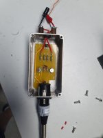
A bit late, but this is the freq response of the 60dB HV balanced attenuator, 100Meg differential impedance, courtesy Demian.
On the 2 x 50k attenuation leg, I need about 2 x 250pF to equalize the response which means I have about 0.5pF in parallel of the 100Meg.
I think that is low enough to not load down the test point on the amp.
Jan
On the 2 x 50k attenuation leg, I need about 2 x 250pF to equalize the response which means I have about 0.5pF in parallel of the 100Meg.
I think that is low enough to not load down the test point on the amp.
Jan
Attachments
Jan,
What input voltage was used to test this attenuator, was it up to the full 5000 Volt ?
Hans
What input voltage was used to test this attenuator, was it up to the full 5000 Volt ?
Hans
The board in this metal box should have a distance of minimum 5cm to be able to handle 5kV, so should any wiring incl. The resistors ( dubble that for the differential signals). Therefore the size of the resistors alone is a problem here. Also the voltage coefficent needs to be checked if you like to have usefull measurement results.
Its very difficult to build something like this from scratch. Accuracy is an even bigger challenge. The mockup I sent seemed pretty accurate to 3 KV. I would not expect absolute accuracy without some fiddling. HV dividers can get quite complex. In any case I don't think the goal here is .1% accuracy, more of waveform monitoring and significant distortion identification.
These are more accurate with a substantial cost: http://www.ohm-labs.com/high-voltage-dividers/kvvb-compact-divider.html There are other, even more scifi, version at their site.
Or a pair of these: https://www.tek.com/en/high-voltage-probe-manual/p6015a again a lot of $$$.
These are more accurate with a substantial cost: http://www.ohm-labs.com/high-voltage-dividers/kvvb-compact-divider.html There are other, even more scifi, version at their site.
Or a pair of these: https://www.tek.com/en/high-voltage-probe-manual/p6015a again a lot of $$$.
O.k. Thx for your comment.Its very difficult to build something like this from scratch. Accuracy is an even bigger challenge. The mockup I sent seemed pretty accurate to 3 KV. I would not expect absolute accuracy without some fiddling. HV dividers can get quite complex. In any case I don't think the goal here is .1% accuracy, more of waveform monitoring and significant distortion identification.
These are more accurate with a substantial cost: http://www.ohm-labs.com/high-voltage-dividers/kvvb-compact-divider.html There are other, even more scifi, version at their site.
Or a pair of these: https://www.tek.com/en/high-voltage-probe-manual/p6015a again a lot of $$$.
Hans
I did finally get the time to wind up some inductors more similar to the size and proportions of the actual delay-line inductors.
The new measurements show that the original estimate was not too far off.
New coupling factor estimates are:
K=0.25 (adjacent inductors)
K=0.05 (inductors one place further down the line)
Hi bolserst, do you think it is possible to make new coils with the correct values and fitting the existing PCBs? I am asking since one of mine is probably broken, and that may be happening to a few others as well, as these speakers are aging. Not sure if that would be reasonably feasible though....
Alfred, I have some spare delay line assemblies from 63's, I could see if I can remove a coil and send it your way.
They are all the same, right?
Jan
They are all the same, right?
Jan
yes, they are all the same it seems, and that is a very kind offer!!! I will disassemble the speaker and check how many coils are broken (I think it is only one). I will PM you shortly.
Still, I think it would probably be a good idea to have an idea for a true replacement part, as over time many more of them might break.
(The alternative - of course - would be to go the Jan Didden way 😀 with an analog delay line and direct drive for each segment, but that would be a bigger project.....)
- Home
- Loudspeakers
- Planars & Exotics
- QUAD 63 (and later) Delay Line Inductors