I had the same problem understanding the various graphs.
But when finally doing an on-axis mike recording, all things come together and with the DSP, corrections can simply be made, so Jan is very well prepared.
Hans
But when finally doing an on-axis mike recording, all things come together and with the DSP, corrections can simply be made, so Jan is very well prepared.
Hans
Good morning Hans,
I agree that the numbers probably are not 100% correct, but I believe that the method is correct. Let me explain, also for my own benefit.
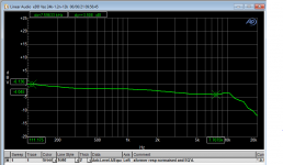
When I drive the speaker with a flat sweep, I get the secondary response as in attachment 1. If my direct drive amp has to provide the exact same acoustic response as the original transformer based, my direct drive amp has to deliver a frequency response as in attachment 1. Agreed?
In that attachment you see that, referenced to 100Hz, at for example 7kHz, the response has to be down by about 4dB.
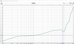
So what I do is invert this response and load it into REW so I get the 2nd attachment. Now the dip at 7kHz has been changed into a peak of 4dB at 7kHz.
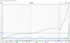
So now when I tell REW to equalize this response to a flat response referred to 100Hz, it will generate a filter set that lowers the 4kHz response by 4dB. The results is shown in the 3rd attachment.
So if I drive the direct drive amp through this filter set (loaded into the miniDSP), a flat sweep at the input of the direct drive amp will show a response at the panels which is identical to the original setup with the step up transformer.
There may be some confusion because the resulting response is shown as flat (with some +/-0.2dB ripples) in the 3rd attachment, but in reality it is the original response at the secondaries.
Have I confused you sufficiently ;-)
Jan
I agree that the numbers probably are not 100% correct, but I believe that the method is correct. Let me explain, also for my own benefit.
When I drive the speaker with a flat sweep, I get the secondary response as in attachment 1. If my direct drive amp has to provide the exact same acoustic response as the original transformer based, my direct drive amp has to deliver a frequency response as in attachment 1. Agreed?
In that attachment you see that, referenced to 100Hz, at for example 7kHz, the response has to be down by about 4dB.
So what I do is invert this response and load it into REW so I get the 2nd attachment. Now the dip at 7kHz has been changed into a peak of 4dB at 7kHz.
So now when I tell REW to equalize this response to a flat response referred to 100Hz, it will generate a filter set that lowers the 4kHz response by 4dB. The results is shown in the 3rd attachment.
So if I drive the direct drive amp through this filter set (loaded into the miniDSP), a flat sweep at the input of the direct drive amp will show a response at the panels which is identical to the original setup with the step up transformer.
There may be some confusion because the resulting response is shown as flat (with some +/-0.2dB ripples) in the 3rd attachment, but in reality it is the original response at the secondaries.
Have I confused you sufficiently ;-)
Jan
Attachments
Jan,
Thanks for the explanation, but this was obvious.
What you did made complete sense, but the point is that I have a problem with the correctness of what your measuring gear was showing, going down by 12dB at 20Khz.
And it is obvious that the accordingly corrected measured curve will be flat when using the same gear.
But as I said, the most important version will be the final on-axis sound recording.
I’m anxiously waiting for that one.
Hans
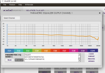
... and then, when I load the REW generated filter file in the miniDSP that was just delivered, I get the originally measured response at the secondaries/panel connections, as measured before. This filter is applied to the direct drive amp so it replicates the original freq response. -4dB @ 7kHz, -12dB @18kHz.
QED. 😎
Jan
QED. 😎
Jan
Attachments
Jan,
Thanks for the explanation, but this was obvious.
What you did made complete sense, but the point is that I have a problem with the correctness of what your measuring gear was showing, going down by 12dB at 20Khz.
And it is obvious that the accordingly corrected measured curve will be flat when using the same gear.
But as I said, the most important version will be the final on-axis sound recording.
I’m anxiously waiting for that one.
Hans
OK, understood. That will have to wait until I finalize the 2nd prototype of the dd amp. Boards on the way ;-)
Jan
Hi Jan,
Great work. I'm following this with much interest.
I have been toying with the idea of DD drive for ESL63 for many years. Actually tried it back in the 80's when I was young and fearless with an old Philips EL36 based valve amplifier I had. It didn't have enough voltage sving and I of course didn't have any measurement equipment. It did play. Just not very loud.
When I got older and perhaps a little wiser or just chicken I didn't dare this due to the high voltages involved. Did exchange some mails some years ago with late TdP about using a valve amplifier with an output transformer to step-up. He didn't think it was a good idea which I can't think why. I know he had made a ESL63-DD for Tony Faulkner.
Perhaps your efforts will tempt me to try. Still have the ESL63.
Cheers,
Mogens
Yes. It is scary ;-) That is one reason I went with a DC coupled amp with +/-2500V power supplies, instead of a single 5000V supply. Half the voltage.
That made the whole front end more complex but I feel it is worth it.
Once it is working as it should and remains in one piece I will give more details about the circuit.
Jan
That made the whole front end more complex but I feel it is worth it.
Once it is working as it should and remains in one piece I will give more details about the circuit.
Jan
True, but now you have two potentially lethal supply rails instead of one. At least you can use a zero output common-mode voltage now, rather than half the supply voltage.
Yes, now I have two rails, but the spacing and isolation requirements are half. For me this is better overall. YMMV of course.
Jan
Jan
Output resistors that is limiting the current to below 3mA would make it safe to touch the panels.
But you more than 3mA to drive the panels, and a resistor would mess up the freq response with the capacitive load part.
Jan
Jan
3mA at 2500V means 7.5Watt.
Probably enough to be lethal, especially with Jan’s superconductive shoulders.
Hans
Probably enough to be lethal, especially with Jan’s superconductive shoulders.
Hans


3mA at 2500V means 7.5Watt.
Probably enough to be lethal
Watts aren't the typical unit of concern when it comes to electrocution. Current is where the action is. Impedance of the body and voltage, of course, influence the amount of current flowing through you, but a focus on simple watts isn't one that's going to provide the best prediction of lethality.
This link gives a basic rundown of the typical hazard ranges
Electric Shock Hazards
Last edited:
If you mean 2500V on ONE plate the power output is 4 times that = 30 watt. So 3mA in one plate is in the ballpark. It is also considered "safe".
3mA at 2500V means 7.5Watt.
Probably enough to be lethal, especially with Jan’s superconductive shoulders.
Hans
Two times. Double the voltage at the same current is 2 x power. But it is separate anyway, you either touch one panel or the other, both at the same time is physically very hard, so its 2500V @ 3mA in your suggestion.
But anyway, as I explained above, 3mA limit is not feasible.
Jan
But anyway, as I explained above, 3mA limit is not feasible.
Jan
Last edited:
2500 V peak per stator is 5 kV peak differential
The impedance plots earlier in this thread show magnitudes of the order of 400 kohm
5 kV/400 kohm = 12.5 mA, so if there were a current limiter in the amplifier, it would have to be set to at least 12.5 mA
If you want to use a series resistor as current limiter, you would presumably want its impedance to be much smaller than that of the loudspeaker, so most of the 2.5 kV peak ends up in the loudspeaker and not across the current limiting resistors.
Accepting 10 % voltage loss, you can allow resistors of 22 kohm per stator, resulting in a perfectly lethal Norton current of just over 110 mA.
Where on Earth does that 3 mA come from?
P=U^2/R is not applicable here; I is constant, V varies.
P = I x V; 2 x V same I is 2 x power. Do we have to spend time on that here??
Jan
P = I x V; 2 x V same I is 2 x power. Do we have to spend time on that here??
Jan
Last edited:
Where on Earth does that 3 mA come from?
Just a random number I guess.
My design is for 12mA peak current. Should be just sufficient.
Jan
Last edited:
- Home
- Loudspeakers
- Planars & Exotics
- QUAD 63 (and later) Delay Line Inductors