If you are agree that the OT ( in general, each trafo) is bi-directional device you can be agree with me about this method.
Then, in addition, we haven't the possibility to get 220 Vrms of signal test ( just as example) with low distortion and right Zsource + frequency sweep until 200 kHz ( as AP do)
About verification, each one can do the test in both ways and discuss the results, of course
I don't need this verification because normally I test the OT only and inside the circuit.
About comparision I can tell you that the shape of each test results with a standard set up is quite similar.
The differences are due the distortion ( and parasitic) of tubes.
But, finally, in this way you can understand the quality of OT alone.
Walter
I report
Walter, can I suggest you use the other thread you linked to to continue discussion on driving the secondary winding, as well as presenting data from OPT's that are not aligned with the Williamson amplifie
No problem when the test set will be ready I will send all info in a new thread.
Finally, the last phrase is incorrect.
This method is valid for ALL OT trafos.
Please, answer to me to me about the concept that each trafo is a bi-directional device and if you are agree.
Walter
Last edited:
Walter, you presented some measurements for an example 5kPP OPT in post #33 - that particular OPT is not aligned with the Williamson amplifier (10k PP plus other characteristics described by Williamson). My comment was about that 5kPP data, not your method.
Happy to chat to you about your method over on the other thread, otherwise it would be threadjacking this thread.
Happy to chat to you about your method over on the other thread, otherwise it would be threadjacking this thread.
But with 10 Vrms on primary with a ratio around 15-20 what do you think to see?
Your value of Thd a low frequency is considered high compared to the level of signal test and this only realted to the core.
If you go at 50% of the rated power of OT you probably reach the 2-3% of THD at low frequency
Walter
Your value of Thd a low frequency is considered high compared to the level of signal test and this only realted to the core.
If you go at 50% of the rated power of OT you probably reach the 2-3% of THD at low frequency
Walter
Walter, what I see are the initial distortion plot results I linked to. As per post#47, the WWFB distortion was noticeably lower. And I do aim to set up a high powered balanced driver to further characterise those OPTs - that was and is still the intent.
TO TR
Hi
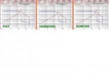
in attach a diagram of the test done with a sw developped inside Audioreview by my collegue Fabrizio.
I spoke about 2017, date of my initial thread.
It is same as yours with REW ( maybe it takes from ARTA the concept to measure the passive components) ) and it is fine so other people can do this ( I am not familiar with REW).
This sw has more info inside respect to REW but is not important for a general use.
The results are exactly the same ( in general) and these test tell us a lot of things except, partially, the quality of iron.
The consifìderation of 45 are fine but for my experience the coupling of pieces moves just a little bit.
I have used different method to put the section of iron perfectly faced (in a p-p) and the final results differ for a bit.
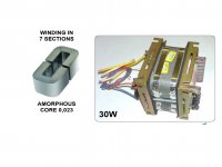
In attach one of the best I have tested, it is ONORI in Italy. The method fo fix the iron is very strong.
And the lamination and material are fine.
In attache the test THD vs freq. with 60 Vrms on primary, 5 watt rms on load, very good results
Walter
Hi
in attach a diagram of the test done with a sw developped inside Audioreview by my collegue Fabrizio.
I spoke about 2017, date of my initial thread.
It is same as yours with REW ( maybe it takes from ARTA the concept to measure the passive components) ) and it is fine so other people can do this ( I am not familiar with REW).
This sw has more info inside respect to REW but is not important for a general use.
The results are exactly the same ( in general) and these test tell us a lot of things except, partially, the quality of iron.
The consifìderation of 45 are fine but for my experience the coupling of pieces moves just a little bit.
I have used different method to put the section of iron perfectly faced (in a p-p) and the final results differ for a bit.
In attach one of the best I have tested, it is ONORI in Italy. The method fo fix the iron is very strong.
And the lamination and material are fine.
In attache the test THD vs freq. with 60 Vrms on primary, 5 watt rms on load, very good results
Walter
Attachments
Last edited:
It's not just the method. If the laminations have different degree of manufacturing tolerances you will get different results no matter what you do to put them together,. You cannot fix the laminations 1 by 1 when you mount the core. Only as a block. In a PP without formal gap, but only the natural air-gap, even if you alternate the Es and Is it is not a guarantee of best result. When you are going to clamp or whatever you always act on the whole core.
The same goes for C cores, if the cut is uneven the air gap will be uneven no matter what you do.
This can explain small differences in distortion at low level.
In reality when this aspect is fine the transformer will be fine also at max rated power, unless it's not properly designed and the core quality is really bad (which you can already see at low level).
The high frequency range is more difficult and lots of output transformers have fast rising distortion already from 10KHz. Often worse than low frequency. Here the tubes can contribute quite a lot as well and probably this might be one reason why Williamson decided to use triode strapped pentodes.
Last edited:
It is also the method, of course.
In my experience when you get a iron with good lamination normally the tolerances are very low and coupling is fine.
If you play with test you can see there aren't differences
I bought Finemet and Metglas for tests and are incredible.
Also the one that my supplier use, 0,1 , double C is fine.
"This can explain small differences in distortion at low level"
In my opinion is not always true.
"The high frequency range is more difficult and lots of output transformers have fast rising distortion already from 10KHz. Often worse than low frequency. "
Looking at the tests on OT charatheristic after the resonace the load became capacitive and this for tubes is a great problem
Walter
In my experience when you get a iron with good lamination normally the tolerances are very low and coupling is fine.
Exactly! "When" is the right word....
You buy one or a small lot of cores (and I am sure you also ask for the best they have) and test...it's totally different story.
When you are a manufacturer this is not always possible. There are other compromises done to keep production smooth. I think this is the subject of this thread. Custom products are not really the target.
That's why I said in the beginning that the Sowter Transformer for the Williamson amplifier is a safer bet than generic 10K transformers. It specifies the distortion level at low and medium frequency. And if it's out of spec you might be able to get it changed. You cannot be certain about generic transformers that do not have this specification.
Looking at the tests on OT charatheristic after the resonace the load became capacitive and this for tubes is a great problem
Walter
After the resonance the load is always capacitive. The load seen at high frequency is always the same:
1) 1KHz or around there can be assumed resistive
2) then at some point, depending on the leakage inductance and capacitances it becomes inductive and the ellipse starts rotating
2)At the resonant frequency (only) it is again purely resistive and then it becomes capacitive
So if you don't want it to be capacitive you need to push the first resonance higher.
Last edited:
So if you don't want it to be capacitive you need to push the first resonance higher.
This is not possible in a normal OT trafo; the resonance will be always in audio frequencies; the resonance, in my tests, are always within 2-4 kHz for the majority of models so the trouble is always present
Totally agree for Sowter.
"Exactly! "When" is the right word...."
Normally I haven't found issue with the types my supplier use and aren't cheaper.
I spoke for myself, of course.
Walter
This is not possible in a normal OT trafo; the resonance will be always in audio frequencies; the resonance, in my tests, are always within 2-4 kHz for the majority of models so the trouble is always present
That is not the first resonance I was thinking about. Are you talking about the resonance that involves the primary inductance instead of the leakage inductance? In that case such a resonance is normally swamped by the resistive elements in the circuit and is not a concern for distortion.
I have never seen clear distortion anomalies at those frequencies.
I bet he's talking about the main resonance between main inductance and overall capacitance. In audio apps we neglect it, because it's swamped by overall low resistance circuit, reducing it's Q factor.
Afterwards the leakage inductance resonates with different possible capacitances. There can be one, there can also be a few. Some can get rolled over by an early capacitive or inductive roll-off.
Afterwards the leakage inductance resonates with different possible capacitances. There can be one, there can also be a few. Some can get rolled over by an early capacitive or inductive roll-off.
The problem is not the resonance itself but the shape of the capacitive front mainly.
On the inductive front the Z is increasing and the job of the tube is more easy in theory ( of course the inductance at low freq. must be reasonable high).
We can add some consideration around the real load, If we think at a bass reflex loudspeaker with two resonance at low frequency.
On the capacitive part the job is more hard proportionally with value of C.
Testing the OT from secondary we use a real resistive Zsource and loaded with a pure resistor, so we can see what happen with different level of signal
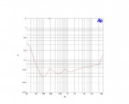
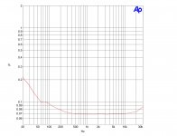
In attach just an example ( this is a proto, not well done, for 300B) of THD vs Freq.
59 volt on primary close to 750 ohm ( almost the Rp of a 300B), around 5 watt.
The shape show that on low frequency there is an issue of iron and Inductance and on mid high an issue with capacitance.
In absolute the value of THD are not so bad but the problem is the shape.
I have measure hundreds of tube amp at Audioreview lab plus others in my lab and I always found a good answer between measurement and listening tests when the shape of this test is not a narrow U but wider
In this case the region with a very low THD is little.
For example ( of the shape) the other one in attach, as reference. The difference is high
And the shape must be same for different level and this is very hard to get.
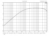
Just for info, in other attach the freq. answer of a assembly (ONLY bobbin) of an OT; intersting!
Walter
On the inductive front the Z is increasing and the job of the tube is more easy in theory ( of course the inductance at low freq. must be reasonable high).
We can add some consideration around the real load, If we think at a bass reflex loudspeaker with two resonance at low frequency.
On the capacitive part the job is more hard proportionally with value of C.
Testing the OT from secondary we use a real resistive Zsource and loaded with a pure resistor, so we can see what happen with different level of signal
In attach just an example ( this is a proto, not well done, for 300B) of THD vs Freq.
59 volt on primary close to 750 ohm ( almost the Rp of a 300B), around 5 watt.
The shape show that on low frequency there is an issue of iron and Inductance and on mid high an issue with capacitance.
In absolute the value of THD are not so bad but the problem is the shape.
I have measure hundreds of tube amp at Audioreview lab plus others in my lab and I always found a good answer between measurement and listening tests when the shape of this test is not a narrow U but wider
In this case the region with a very low THD is little.
For example ( of the shape) the other one in attach, as reference. The difference is high
And the shape must be same for different level and this is very hard to get.
Just for info, in other attach the freq. answer of a assembly (ONLY bobbin) of an OT; intersting!
Walter
Attachments
I don't think the tube will see a reactive load in the midrange. That would mean that the phase would change but this does not happen. For a resistive load, the reflected impedance is resistive for most of the audio band and then getting inductive on both ends. On the high end, outside the audio range for good transformers, it becomes capacitive past the transformer self-resonance. Otherwise you would be in deep deep trouble when applying even a small amount of feedback.
Maybe your problem is that your set-up with the generator in series with the resistive 6-8R load on the secondary is a capacitive load as seen from the primary where you take your measurements.
Maybe your problem is that your set-up with the generator in series with the resistive 6-8R load on the secondary is a capacitive load as seen from the primary where you take your measurements.
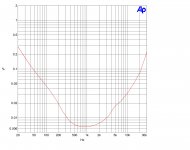
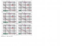
In attach a test of freq. respinse for Onori trafo, se, 3k5 primary, 8 ohm secondary.
The first one is done time ago driving from secondary,
27 volt on primary closed to 750 ohm, 1 watt
on secondary there is a ss amp with 7,5 ohm in series
The second one, done minutes ago is the same trafo with conventional test
AP Sys 2 with 12 volt out ( the max value that can run in this configuration) , Zout= 20 ohm plus 680 ohm in series
Secondary closed to 7,5 ohm, around 500mV out
The results are perfectly comparable.
(I don't know why are so little, I will try to post better image)
Walter
Attachments


Last edited:
Well I think he only wanted to prove his point as you asked earlier at post #35.
I think his method is valid and much easier to implement. 15W into 10K means almost 400 Vrms without distortion to be able to test the transformer at rated power (triode mode). The latter seems quite a challenge to me and really not worth the trouble. No one is embracing the Williamson's philosophy of large amount of GND feedback for ultralow distortion anymore, I think.
I think his method is valid and much easier to implement. 15W into 10K means almost 400 Vrms without distortion to be able to test the transformer at rated power (triode mode). The latter seems quite a challenge to me and really not worth the trouble. No one is embracing the Williamson's philosophy of large amount of GND feedback for ultralow distortion anymore, I think.
Thx to 45 for the post.
It is exactly what I tried to explain.
The method I explained is simply and fast, just to get a good ss amp (commercial).
Then with a simply attenuator 1:10 or 1:100 you can read with a an audio card (normally with a limited acceptance) the results
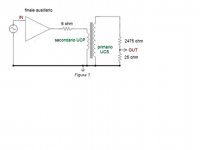
In attach a base circuit with components.
On primary (now act as secondary) there is resistors network where the total Z is the load with a similar value of the Rp of tube.
(the value written are referred to the test done in the article)
Walter
It is exactly what I tried to explain.
The method I explained is simply and fast, just to get a good ss amp (commercial).
Then with a simply attenuator 1:10 or 1:100 you can read with a an audio card (normally with a limited acceptance) the results
In attach a base circuit with components.
On primary (now act as secondary) there is resistors network where the total Z is the load with a similar value of the Rp of tube.
(the value written are referred to the test done in the article)
Walter
Attachments
Thx to 45 for the post.
It is exactly what I tried to explain.
The method I explained is simply and fast, just to get a good ss amp (commercial).
Then with a simply attenuator 1:10 or 1:100 you can read with a an audio card (normally with a limited acceptance) the results
In attach a base circuit with components.
On primary (now act as secondary) there is resistors network where the total Z is the load with a similar value of the Rp of tube.
(the value written are referred to the test done in the article)
Walter
Solid state driving the transformer is not the same as tubes ... ok you can draw some conclusions comparing some output transformers , maybe you could tell which is better , but the actual frequency response will be much different
Solid state driving the transformer is not the same as tubes ... ok you can draw some conclusions comparing some output transformers , maybe you could tell which is better , but the actual frequency response will be much different
Hi
the main purpose of the test is to check the trafo itself outside any type of circuit.
Ans this is the only way to get a good results from min to max permissible wattage reading response and, most important, THD vs Frequency.
For each type of trafo; I am preparing also a test set with the bias current to test the SE
I can tell you that also the changes with or without are non so different, most of the problems in low frequencies are related to iron quality
We done something in the past, in attach a test on one proto with Litz wire and another with classic, Ibias e non bias
Walter
Attachments
Last edited:
- Home
- Amplifiers
- Tubes / Valves
- OPT Characterization