 Some discussion has been split from here - Measurements on output transformers for the Williamson amp
to 50AE
the use of a ss amp is due the very low Zou that they normally have.
In some case it vaires from 50 to 100 mohm; the other thing is the frequency answer where we can see also if the Zout of the ss amp is resisite or reactive.
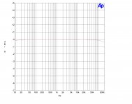
In attach the test of the one I use ( I am working on it to get a better THD vs Freq.), 8 watt on 8 ohm.
It is flat from 10 to 200 kHz.
With this spec when you connect the resistor in series to ss amp pratically the generator is perfectly resisitive; also when you close the primary with a resistor with a value almost similar to Rp of the tube involed you complete a perfect test set of the OT trafo
So the results are related to it.
If you have a OT with a ratio of 30, and you have a test signal of 8w / 8ohm means that on primary you will have 240 Vrms!
With a standard measurement wich generator can delivery this swing with the same Zout?
The values are theorical because some loss are found but they are real.
Walter
the use of a ss amp is due the very low Zou that they normally have.
In some case it vaires from 50 to 100 mohm; the other thing is the frequency answer where we can see also if the Zout of the ss amp is resisite or reactive.
In attach the test of the one I use ( I am working on it to get a better THD vs Freq.), 8 watt on 8 ohm.
It is flat from 10 to 200 kHz.
With this spec when you connect the resistor in series to ss amp pratically the generator is perfectly resisitive; also when you close the primary with a resistor with a value almost similar to Rp of the tube involed you complete a perfect test set of the OT trafo
So the results are related to it.
If you have a OT with a ratio of 30, and you have a test signal of 8w / 8ohm means that on primary you will have 240 Vrms!
With a standard measurement wich generator can delivery this swing with the same Zout?
The values are theorical because some loss are found but they are real.
Walter
Attachments
Yes Waltube, but the question was addressed to forum member Depanatoru from post #158.
Otherwise a transformer must act like a mirror, impedance wise. I see no reason why you should not get exactly the same measurements if you keep primary and secondary parameters equivalent, following the impedance ratio.
Otherwise a transformer must act like a mirror, impedance wise. I see no reason why you should not get exactly the same measurements if you keep primary and secondary parameters equivalent, following the impedance ratio.
Last edited:
Normally I test in double way.
First following exactly the ratio, then with equivalent ( or close) load same as Rp of tube.
On this thread there was a discussion about this aspect and some good considerations were done.
Walter
First following exactly the ratio, then with equivalent ( or close) load same as Rp of tube.
On this thread there was a discussion about this aspect and some good considerations were done.
Walter
I have to be honest...
When I have characterised a OPT, I have used a signal generator, and a source resistor which is chosen to be close to the expected plate resistance of the valve to be used (at the correct operating point etc), and loaded the secondary with a resistive load equivalent to the loudspeaker.
It's good enough to give me very satisfactory frequency response plots to show resonances both in and out of band.
I dont know if there is any need to complicate it any further
A good generator can delivery around 20 V rms.
I have two AP, the max Vout is 12 volt balanced. Zout 20 and 600 ohm
I have also R&S Apn 62 that reach 20 volts with Zout variable from 10 ohms to 2 kohms, beautiful
Plus HP 339A
This is a limit.
A simple trafo for 300B has around 25-27 as ratio.
With 20 volt on primary what do you think you see ?
In my opinion the most important test is not the frequency answer, less or more now the OT, normally, are decent stuff.
Also for resonance, now it is difficult to find a prrible trafo.
For me the most important test is the THD vs Frequency at all level until the max declared.
Looking at the shape of the test it is possible to understand the real quality of OT
First for the iron then for the topology of coils ( parasitic)
And setting the test set is not so complicated!
🙂
Walter
Try driving the primary side and look at what shows up on the secondary side instead. You may need to swing a bit more drive signal voltage to accomplish that.
As above, that is the route I normally take.
My signal generator can output 20V p-p into high Z load, which I agree is not close to the real primary excitation voltage the OPT would experience in a real circuit.
Also, without some clever work, the effect of DC bias on Frequency response is not easily tested.
But, in some of my circuits, the p-p output swing has been in the region of 1/3rd HT voltage, perhaps 100V, and that is at maximum output. (Ok so this is 3W SET).
I don't attempt to measure THD of the OPT in this bench tip test setup.
More often than not, I have found cancellation effects, between the valve output signal THD and the THD generated by the OPT often resulting in a lower THD measurement at the loudspeaker terminal, than the anode connection.
When looking for resonances the excitation level is largely irrelevant. If it's high enough Q to care about, then itll be easily excited.
Need to swing more volts?
Why not just hook up something like Ixys 10M90S, 10M45S to 300V DC supply, and modulate the gate with the signal generator.
Could even get fancy and use another 10M45S as CCS 'anode' load, on top of the Follower and set to your OPT operation DC bias conditions.
Last edited:
Need to swing more volts?
Why not just hook up something like Ixys 10M90S, 10M45S to 300V DC supply, and modulate the gate with the signal generator.
Could even get fancy and use another 10M45S as CCS 'anode' load, on top of the Follower and set to your OPT operation DC bias conditions.
And do you think this is more easy?
As told before in other post I will prepare a test set up with the possibility ot inject the bias current to show what happen in a s.e.
Then, you can test the OT trafo as you want.
But is not the complete and exaustive test.
Due the fact that thousand of posts are wrote about the quality of trafo and in which way someone can understand the quality ot them I am surprise about the comment on the procedure I described
Test it before give a sentence.
Maybe you will falling in love!
🙂
Walter
Try driving the primary side and look at what shows up on the secondary side instead. You may need to swing a bit more drive signal voltage to accomplish that.
Look at post 155.
12 Vrms from AP Sys2
Walter
Perhaps it would be no easier, true.
Maybe the same test can be performed driving the secondary with load, reading the primary output, with correct load/source Z?
I have not tried, so my comment is postulation only
Maybe the same test can be performed driving the secondary with load, reading the primary output, with correct load/source Z?
I have not tried, so my comment is postulation only
Need to swing more volts?
Why not just hook up something like Ixys 10M90S, 10M45S to 300V DC supply, and modulate the gate with the signal generator.
Could even get fancy and use another 10M45S as CCS 'anode' load, on top of the Follower and set to your OPT operation DC bias conditions.
But you want a controlled impedance driving it - such a simple “amplifier” may or may not get you there. And might generate distortion you don’t want. Need a lot of volts? Bridge one of the big solid state amps (like a Phase Linear or QSC). They will put out 50% more voltage than “normal” into a high impedance load. You’ll be putting a multi-k ohm resistor in series as well (need to double terminate), so the load on the amp is nil making it put out darn near the full supply voltage.
Double termination (impedance on both sides) is the key to characterizing it. In theory, you SHOULD be able to excite either the primary or secondary. Why? It is what my prof used to call an “LLPFB” network. Lumped, linear, finite, passive, and bilateral. Transformers are, until you get into RF frequency where they become distributed networks. But even then, they can mostly be characterized from either side if they are “low loss”. So you want to look at it from the standpoint of being driven by pentode Rp (which is higher) instead of the rated secondary Z, to get a true picture of frequency response IN YOUR AMP? Fine. Adjust the source (secondary) series impedance where you drive it by the same factor. Maybe 20 to 100 ohms instead of 8. You should know what your Rp is (or at least the assumption of what you want). Terminate the secondary with rated Z. You will extract the same model from the data as if you had driven it from Rp on the primary side with rated Z on the secondary. That’s how the math works. If things go nonlinear, it will still be *close*. Drive it to rated power at the secondary under such conditions and all your first order nonlinearities will show up. Higher order will be off somewhat, because of the breakdown of the LLPFB assumption. If you need it more exact than that, measure your whole completed amplifier.
At very high Rp you will still need a BIG amplifier to generate enough voltage to get to rated power with a high series R. Keep your Phase Linear handy.

A typical 300W stereo ss professional PA amp from the 1990's has a power supply rail of about +/-85Vdc, and a 600W amp would have about +/-110 to 110Vdc. Depending on the amp, it probably has THD < 0.01% at low power. Many such amps come with bridge mode, so have unbalanced to balanced conversion circuitry built in. Those amps are often cheaply sold off on ebay as no one wants them anymore.
With a +/-110Vdc rail, the amps are likely to drive about 150Vrms across a PP primary, so may get a test jig up to a drive level of 6W with a 3k5 ohm PP as in post #155. Although well short of the power rating of the OPT, it could be a simple way to compare the reciprocity of primary side versus secondary side OPT testing.
Edit: I see wg_ski has just suggested the same concept.
Such amplifiers can be considered “test equipment”. Even if you would never consider such an amp in your main music system (allergies to sand, fear of fans, any number of reasons), they are worth buying. The heavy iron ones are being ditched for a song these days. And they are the ones you would want on your test bench, for times when you would be driving a heavy load and one of those modern class D things might explode under the stress.
Each opinion is welcome.
But after the words I suppose that a test results of the theory that trobbins and other have wrote would be publishd with the same level of test set and accuracy I sent.
Otherwise remain words.
I have done the test from primary with different amps; in Audioreview lab there is one amp used for the tests on loudspeaker that can deliver 600+600 watt rms ( is a Rotel, not remember the type), and can be configured bridge.
But the use of a good ss amp, that can deliver 20 volt rms on 8 ohm ( as minimum) with large freq. response and low THD vs. frequency is much better for the use as driver of the secondary.
With less stress and better results.
Walter
Waltube, are you saying you have made measurements on an OPT when driving the primary side, and when driving the secondary side, both under the same equivalent conditions, and reported comprehensive details of the setup and results?
Your previous post indicates you have a convenient set up (600W stereo amp with bridge circuitry) to do something like a 5W level comparison test, even if higher power level tests are beyond your capabilities.
You keep reiterating that a secondary side driver test 'is much better' and provides 'better results', but without a detailed comparison of primary versus secondary side driving, your comments 'remain words'.
No, you are playing.
I wrote that the level are different and the results are comparable due the same face of response.
Also, You said that is not necessary to get a high voltage to understand the trafo
And the comparision I made is enough to understand that the method to drive the secondary if fine.
Another thing, I am always waiting your answer about my question if a trafo is a bi-directional device.
Last, if you are not agree please demonstrate with test lab that my method is wrong and please show the right way.
Walter
Where did I say that ??You said that is not necessary to get a high voltage to understand the trafo .
'fine' is very different than 'better', as better implies you can show it is better.And the comparision I made is enough to understand that the method to drive the secondary if fine.
Every transformer is bidirectional to some level, but not everything that goes in through one port comes out the other port, and vice versa. Clarifying the differences are important if you want to make comparisons. If you don't want to make a rigorous comparison then that's fine - as fine as your proposed method - but perhaps keep it at fine, and not better until you can confirm and detail what the differences are and why, otherwise people will suggest it is related to marketing hype.Another thing, I am always waiting your answer about my question if a trafo is a bi-directional device.
I think this is where you misinterpret the situation - there is no right or wrong way, just two ways of testing. So far I've only used the primary driven method, because that is what has been used for many decades, and as far as making comparisons go the key is to use the same method, or to know exactly where and why another method can be used. My aim has been to measure classic transformers from the days of yore, of which some had been measured using methods that I have tried to replicate.Last, if you are not agree please demonstrate with test lab that my method is wrong and please show the right way.
Last edited:
- Home
- Amplifiers
- Tubes / Valves
- OPT Characterization